YSi-SP_Ope_E.pdf - 第91页
2-54 2 Operation 3.6.14 Screen of function restriction for Operator Select according to the procedure as [Function/Setting] → [Disp Relation] in Main displa y , and push [Function Restriction] for Operator , then the pop…
2-53
2
Operation
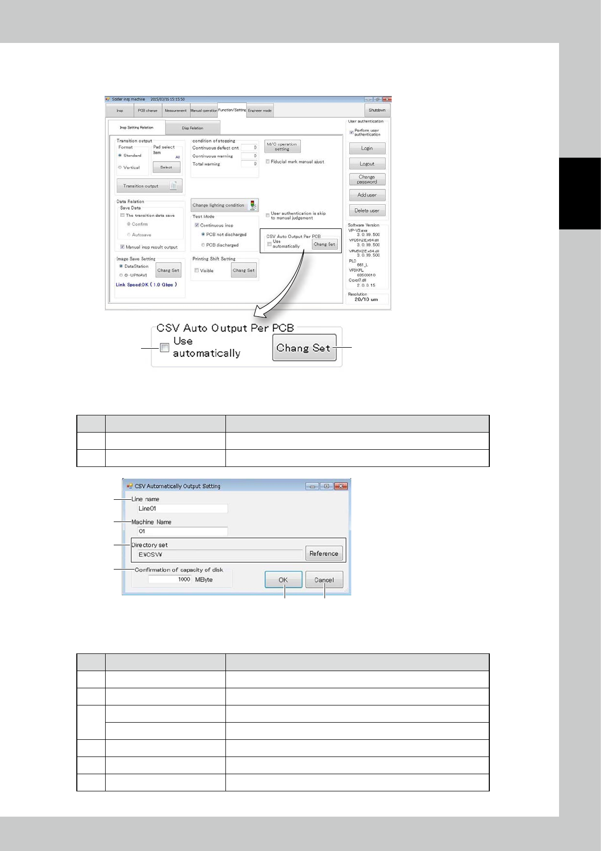
3.6.13 CSV Auto Output Per PCB
Items displayed on the CSV Auto Output Per PCB ,and functions are described.
1
2
24271-KMN-00
■
Explanation of a screen
No Name Content
1 Use Auto Output Per PCB Place check mark for use auto output per PCB.
2 Change Set Changing the setting for CSV output.
1
2
3
4
5 6
24272-KMN-00
■
Explanation of a screen
No Name Content
1 Line name Setting up the line name for CSV output.
2 Machine name Setting up the machine name for CSV output.
3
Directory set Displaying the directory for CSV output.
[Reference] button Changing the directory for CSV output.
4 Confirmation of Capacity of disk When it approaches full up the capacity, the error message is displayed.
5 [OK] button Execution of setting.
6 [Cancel] button Canceling the setting.
2-54
2
Operation
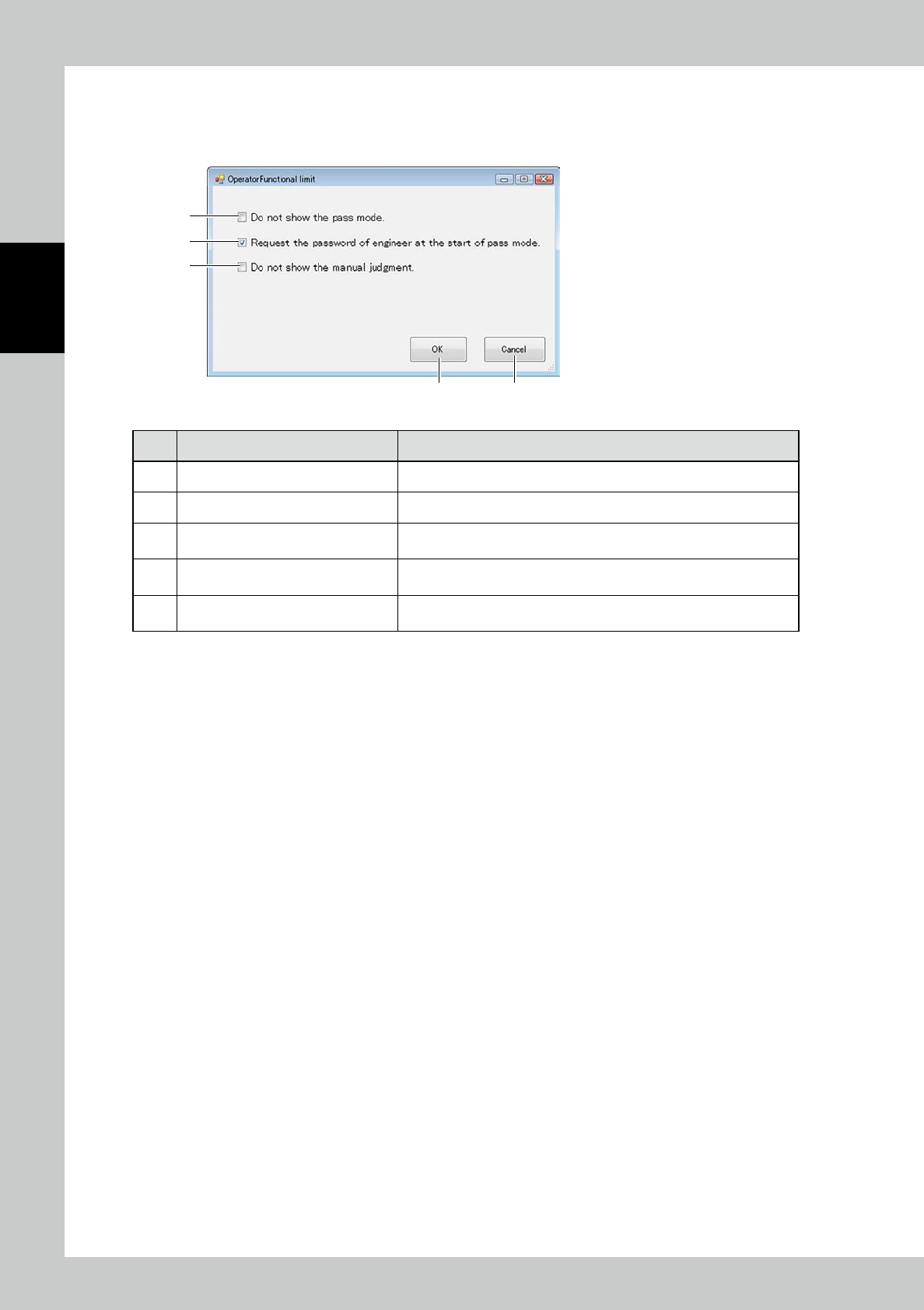
3.6.14 Screen of function restriction for Operator
Select according to the procedure as [Function/Setting]
→
[Disp Relation] in Main display, and push [Function
Restriction] for Operator, then the pop-up of Function Restriction for Operator is displayed.
3
4
5
1 2
24273-KMN-00
No Description Description of displayed item and functions
1 [OK] button Execution of setting.
2 [Cancel] button Canceling the setting.
3 Do not show the path mode.
When checked, Pass mode does not appear in the pull-down menu of
inspection mode under the log-in as Operator.
4
Request the password of engineer at
the start of pass mode
When checked, the password request message for Engineer Authority is
displayed at the start of Pass mode inspection.
5 Do not show the manual judgment.
When checked, when you login the operator, Manual Judge-related
display does not appear.
2-55
2
Operation
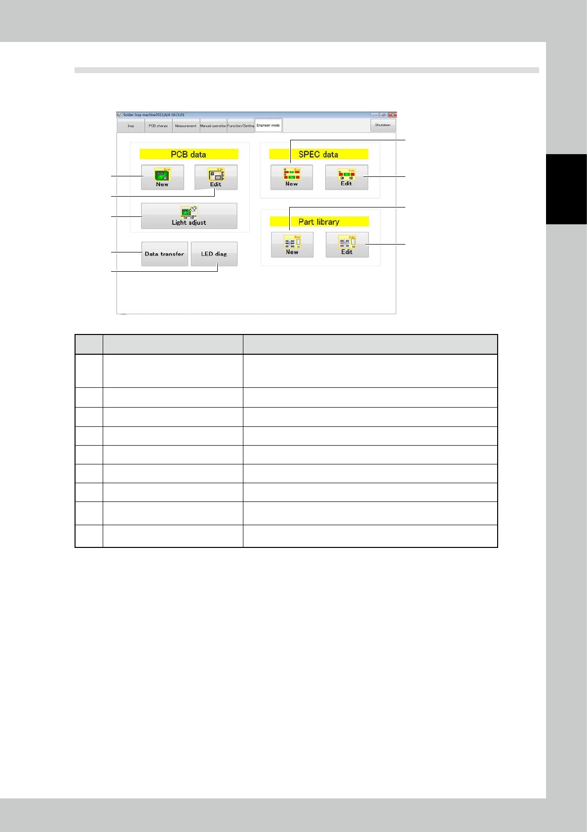
3.7 Engineer Mode
Items displayed on the engineer mode screen and functions are described. You can create or edit inspection
programs and various pieces of data on the engineer mode screen.
3
8
9
4
5
6
7
1
2
24274-KMN-00
No Description Refer to
1 New PCB data is created.
For the creation method using a printed PCB, refer to "4.1 Creating new
PCB data (printed PCB)" in this volume. In other cases, refer to Section
3.2 in the Data Station Volume.
2 Existing PCB data is edited. For details, refer to "4.2 Editing PCB Data" of this volume.
3 The light intensity is adjusted. For details, refer to "4.2.3 Light Intensity Adjustment" in this volume.
4 New spec data is created. For details, refer to Section 3.4 in the Data Station Volume.
5 Existing spec data is edited. For details, refer to Section 3.4 in the Data Station Volume.
6 A new parts library is created. For details, refer to Section 3.5 in the Data Station Volume.
7 An existing parts library is edited. For details, refer to Section 3.5 in the Data Station Volume.
8 Data transfer
Various data can be transferred to the data station.
(Refer to "3.7.1 Data transfer".)
9 LED diag (Option)
Problems in the LED brightness can be checked. (Refer to "3.7.2 LED
diag (Option)".)