YSi-SP_Ope_E.pdf - 第50页
2-13 2 Operation 2. Next, touc h the second point. Another red cross is displa yed together with a red rectangle ha ving the two points as vertices. T he rectangle indicates the measurement range. 2 24213-KMN-00 3. If y …
2-12
2
Operation
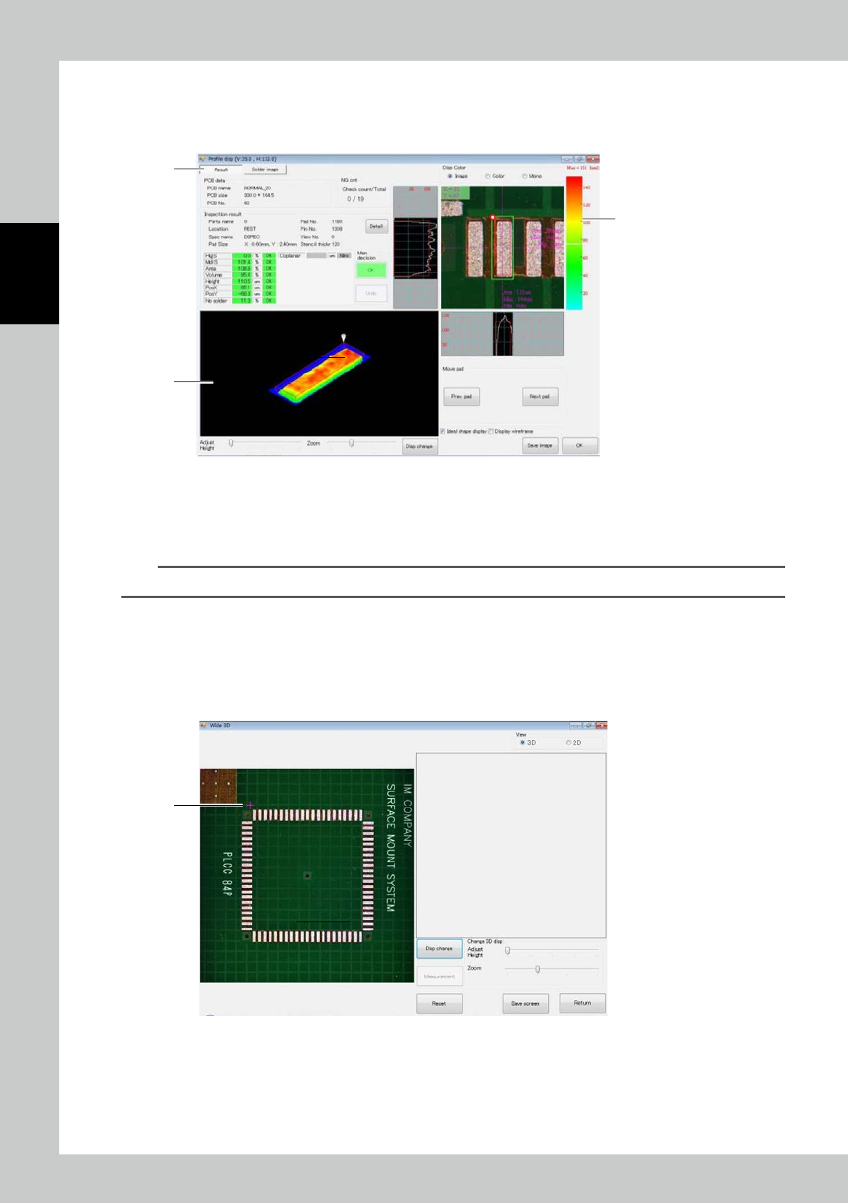
a. Profile display
Touch the [Profile disp] button or touch the desired pad on the field of view screen or each pad screen twice. The screen
shown below is displayed.
1
3
2
24211-KMN-00
1. This is a 3D image of the solder. Slide a finger along the image to change the displaying angle vertically or horizontally
over 360
°
as you need.
2. The solder height is indicated with the color gradation. (Red [high] - blue [low])
3. This is the pad inspection result.
TIP
For details of profile display screen, refer to "3.4.1 Profile Screen".
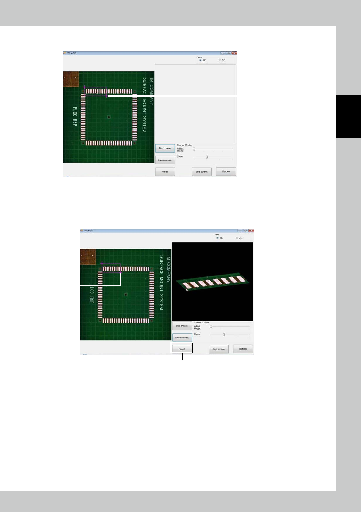
b. Wide 3D
Touch the [Wide 3D] button to display the screen shown below. With Wide 3D, you can view the 3D image of a desired
area.
Select the measurement range with the image displayed on the left side.
1. Determine the starting point. Touch the desired starting point. A red cross is displayed.
1
24212-KMN-00
2-13
2
Operation
2. Next, touch the second point. Another red cross is displayed together with a red rectangle having the two points as
vertices. The rectangle indicates the measurement range.
2
24213-KMN-00
3. If you touch another point in the state of screen 2), the second point moves. You can thus adjust the range while fixing
the starting point.
4. To rework from designation of the starting point, touch the [Reset] button.
After selecting the range, touch the [Measurement] button. The 3D image of the selected range appears on the right
side screen.
3
4
24214-KMN-00
2-14
2
Operation
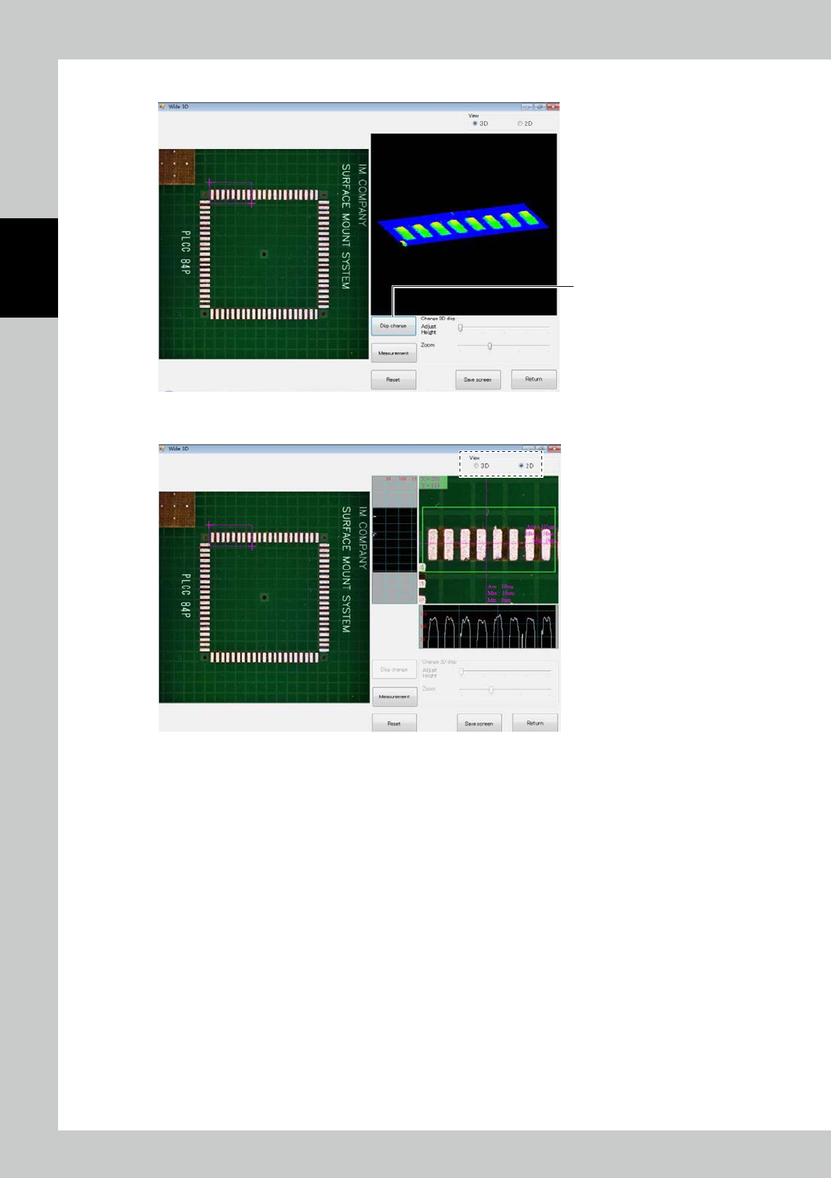
5. Touch the [Disp change] button to change the image to the color gradation height indication image.
5
24215-KMN-00
By checkmarking "2D," you can switch to the cross-section shape display.
24216-KMN-00