YSi-SP_Ope_E.pdf - 第41页
2-4 2 Operation 2. Operation Procedure 2.1 Flow of Inspection T he flow of inspection is shown belo w . (T he reference number for each item indicates the section number .) Flow of Inspection Turn the main body on to sta…
2-3
2
Operation
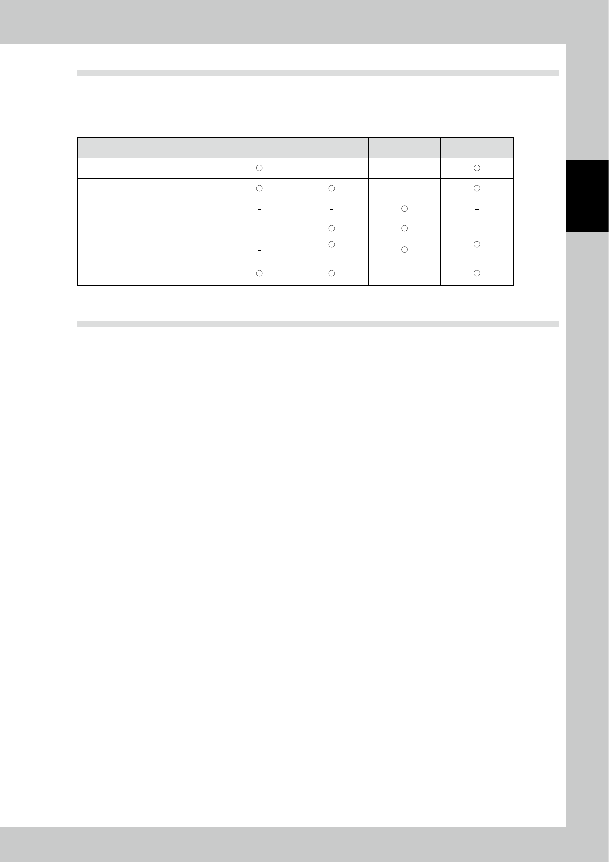
1.3 Tower Light Display
The tower light of the inspection machine has built-in 3-color LEDs and a buzzer.
(3-color LEDs: red at the top, yellow in the center and green at the bottom)
The lighting conditions of the tower light are shown below.
Tower light lighting condition Red Yellow Green Buzzer
At emergency stop
Upon continuous faults
During automatic operation
When a faulty PCB is ejected
Upon a warning
(5sec)
(5sec)
Upon stoppage due to continuous
warnings
1.4 Emergency Stop
Press the emergency stop button located on the right side of the front panel of the main body to stop the
equipment immediately with a buzzer sound. Use the switch to stop in an emergency.
After an emergency stop, follow the procedure below to restore.
1) Touch the [RESET] button on the screen to stop the buzzer.
2) Reset the emergency stop switch. (Turn it in the direction of arrows.)
3) Touch the [RESET] button again and check that the [RESET] button is unlit.
2-4
2
Operation
2. Operation Procedure
2.1 Flow of Inspection
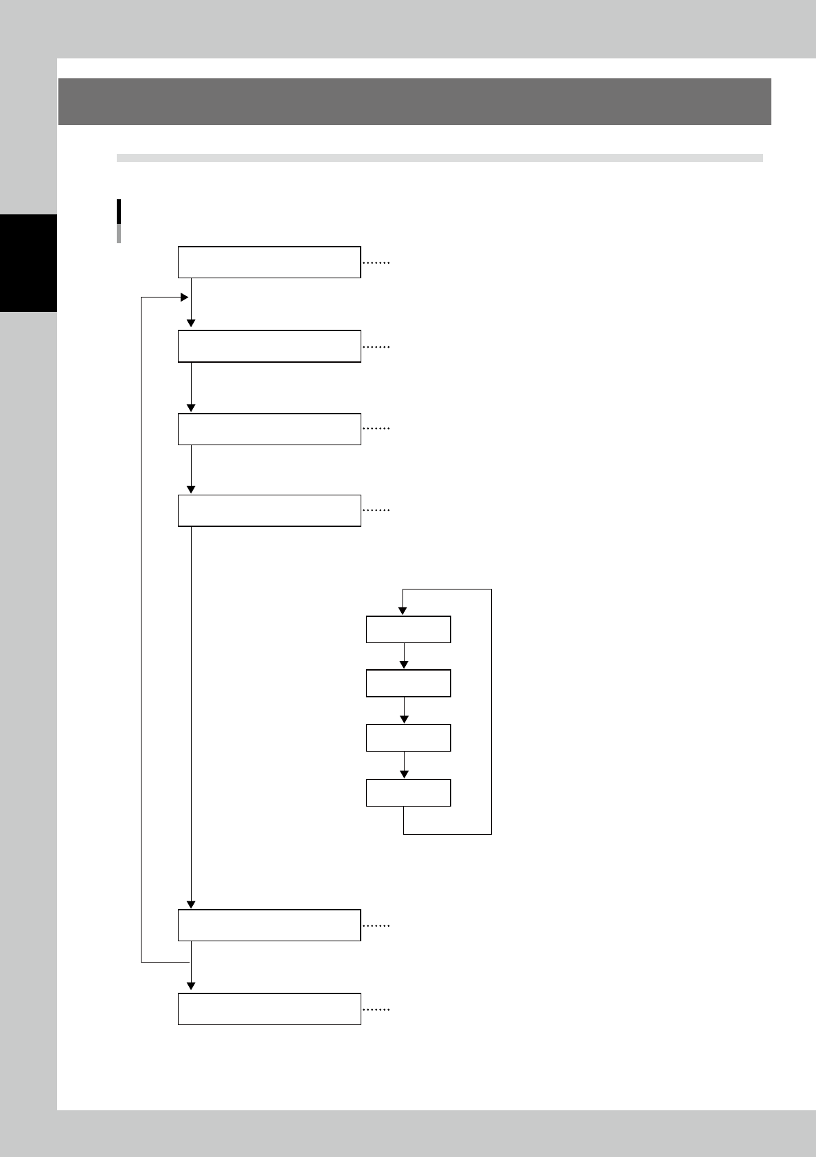
The flow of inspection is shown below. (The reference number for each item indicates the section number.)
Flow of Inspection
Turn the main body on to start the equipment
Select the inspection program for the PCB to be
inspected.
The PCB is loaded into the main body of the machine
in the standalone inspection. This step is unnecessary
for automatic operation.
Inspect continuously while communicating machines
in the pre-and post-processes.
Store the transition data of inspection.
Turn the main body off.
Startup of inspection machine
PCB loading
Inspection and Confirmation
Inspection machine shutdown
(Refer to section 2.3)
(Refer to section 2.4)
(Refer to section 2.5)
(Refer to section 2.6)
(Refer to section 3.5 in “Data Station Volume”)
(Refer to section 2.7)
PCB loading
Inspection
Result display
PCB unloading
The figure indicates
automatic inspection.
(See the next page.)
PCB change
Storing transition data
23203-KMN-00
2-5
2
Operation
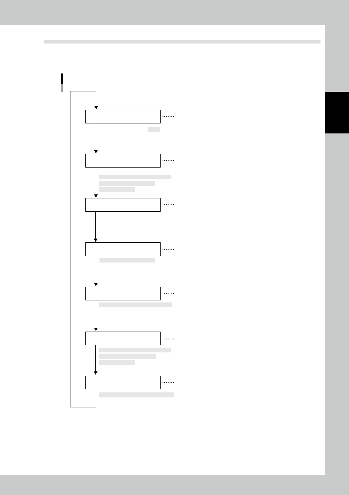
2.2 Operation of One Cycle
In the automatic inspection, inspection is repeated automatically in the order of the arrows shown in the figure
below. The operation method displayed under each operation item indicates the operation method for
standalone inspection.
Operation of One Cycle
PCB transfer into main body
PCB clamp
RDY signal output to
pre-process machines
[Manual operation] → [PCB transfer] →
[Travel to transfer position] →
None
Execution of inspection
Automatic process after fiducial mark check
Fiducial mark confirmation
Touch [Inspection execution]
Inspection result display
Automatically displayed after inspection
PCB unloading
[Manual operation] → [PCB transfer] →
[Travel to transfer position] →
[PCB load/unload]
[PCB load/unload]
The inspection machine issues an RDY signal
when it is ready to inspect a PCB. (No signal is
issued during standalone inspection.)
When the sensor detects a PCB at the loading
port of the inspection machine, the belt is
driven to load the PCB.
The PCB is clamped and fixed when it reaches
the inside of the inspection machine.
The fiducial marks are checked prior to inspection
to give an offset to the inspection program.
Inspection is executed according to the division of
the filed of view on the screen of the main body.
After inspection is finished correctly, the XY table
moves to the loading position. At this time, the
PCB is unloaded upon an RDY signal sent from
the post-process, or it is retained inside the
inspection machine if the signal is not issued.
The inspection result is displayed in the screen
and the machine is ready for inspection of the
next PCB.
23205-KMN-00