YSi-SP_Ope_E.pdf - 第111页
2-74 2 Operation 3. Fiducial mark T he position and size of the fiducial mark are changed. 1. T ouch the [Fiducial mk] button. A field of view including a fiducial mark is selected. 2. T ouch the frame enclosing the fidu…
2-73
2
Operation
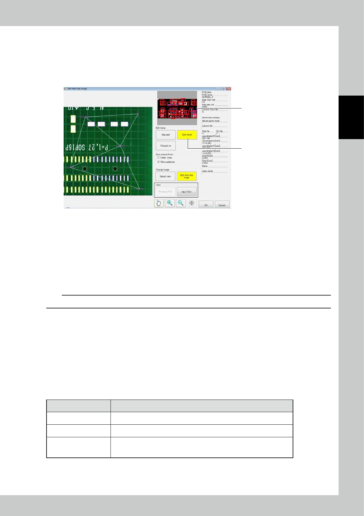
2. Zero level
The zero level is one of references for the measurement of the pad position. A triangular plane is created using the
nearest three zero levels of a pad, so that the accurate position of the pad is measured. The zero level editing method is
described in this section.
1. Touch the [Zero level] button.
2. Select the field of view. Select directly in the image of the whole PCB, or use the [Previous FOV] or [Next FOV] button.
1
2
242A4-KMN-00
a. Extended zero level function
[Jump to undefined view]
After placing a check mark here, touch the [Previous FOV] or [Next FOV] button to display only fields of view
including pads having zero levels fewer than three. If three or more zero levels are specified for all pads, the touch of
the [Previous FOV] or [Next FOV] button moves to the previous or next field of view.
[Guidance display]
The triangular plane consisting of zero levels is displayed. The plane is indicated with white lines during regular
operation. Triangular planes having an acute angle of ≥ 30° and < 40° is indicated with yellow lines, and those having
an acute angle < 30° are indicated with red lines. Acute angles deteriorate the accuracy of zero level.
TIP
Guidance display is not shown if the automatic reference is effective.
b. Zero level editing
Select the field of view to be edited, using the extended zero level function described above or in another way. The
editing method includes the following variations similarly to inspection pad editing.
[Editing on screen]
Select the zero level to be moved or enlarged or shrunk. You can edit the frame position and size in the similar way to
auto shape editing.
[Right button click]
Use the accessory mouse of the inspection machine to edit.
Designate the range and click the right mouse button to execute menu items shown below.
■
Menu displayed upon the click of the right mouse button
Menu option Function
Add A new zero level is added.
Del area Designate an area including multiple zero levels and delete.
Change over pattern / resist
In case of an inspection program created through designation of pattern and resist
with automatic zero level, the pattern and resist references can be switched. Or
double click on the desired zero level to switch the pattern and resist similarly.
After finishing editing, edit the inspection pad or fiducial mark, or touch the [OK] button to save changes, then touch the
[Edit complete] button.
2-74
2
Operation
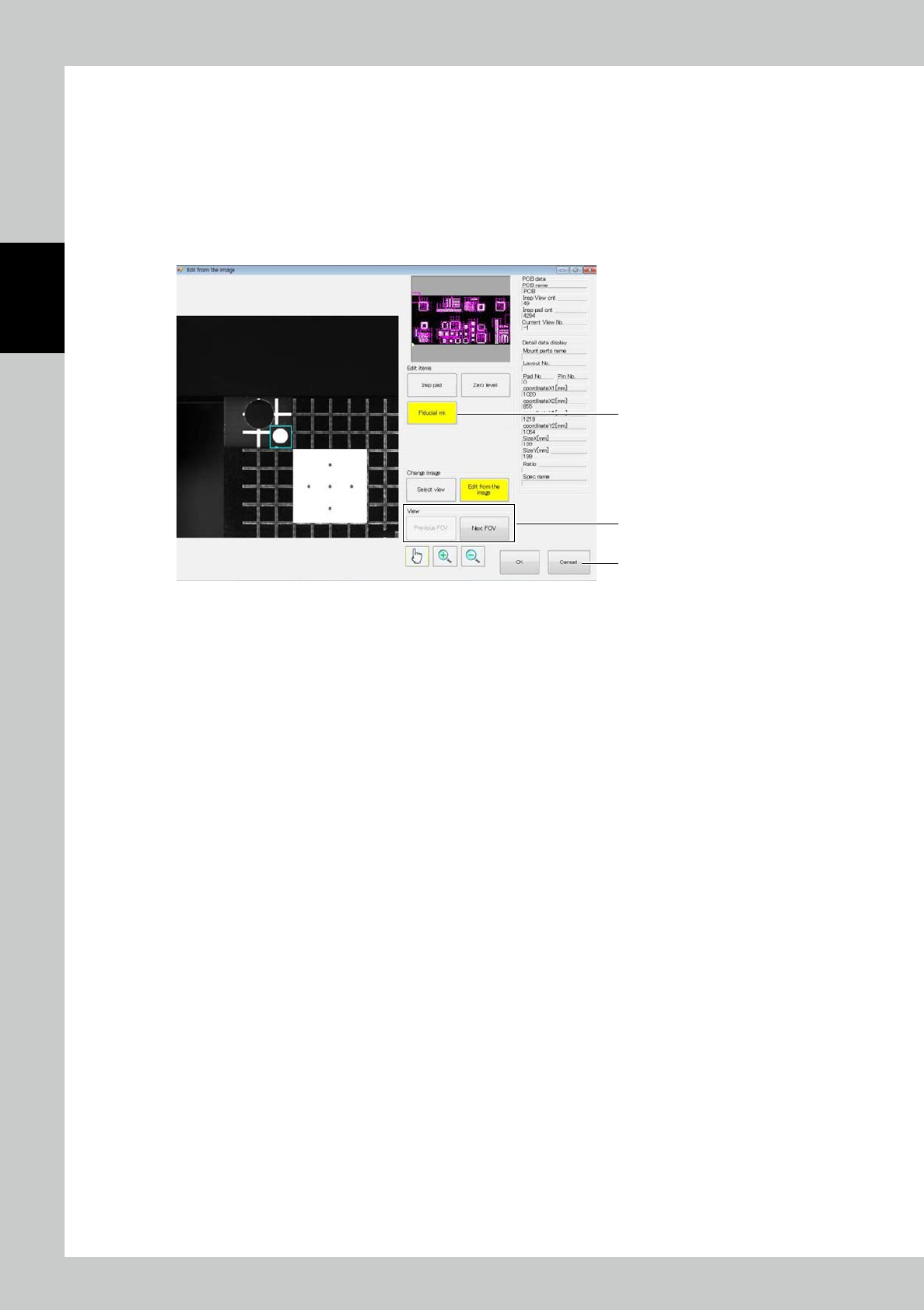
3. Fiducial mark
The position and size of the fiducial mark are changed.
1. Touch the [Fiducial mk] button. A field of view including a fiducial mark is selected.
2. Touch the frame enclosing the fiducial mark on the screen to enable editing.
3. Edit the position and size of the frame in the similar procedure to auto shape editing.
4. The [Previous FOV] or [Next FOV] button to display another fiducial mark and continue to edit.
5. After finishing editing, edit the inspection pad or fiducial mark or touch the [Save] button to save changes, then touch
the [Exit complete] button.
1
4
5
242A5-KMN-00
4.2.2 PCB Editing
Edit the PCB. (For details, refer to Section 3.3 in the Data Station Volume.)
2-75
2
Operation
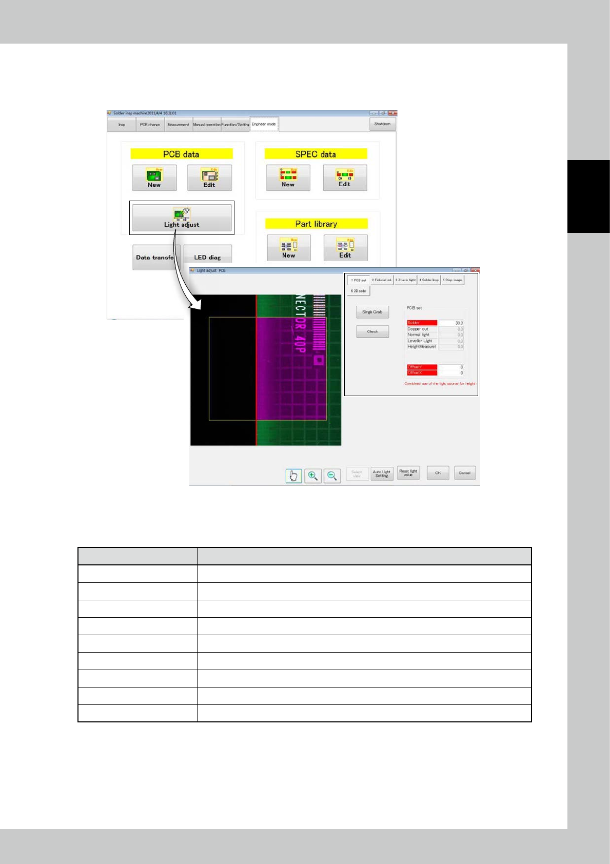
4.2.3 Light Intensity Adjustment
Adjust the light intensity for inspection.
Touch the PCB data [Light adjust] button on the engineer mode screen.
242A6-KMN-00
Light Adjustment has the following seven (7) items on the menu.Light intensity adjustment includes nine menus
as shown in the screen above. Touch the button to select the desired one.
■
Light intensity adjustment menu
Menu option Function
[PCB set] Adjust the light intensity for detecting the PCB edge.
[Fiducial mk1] Adjust the light intensity used for the fiducial mark.
[DSP image] Adjust the light intensity related to the regular camera image.
[Solder extraction] Adjust the light intensity used to extract solder.
[3D inspection] Adjust the light intensity used for 3D inspection.
[Z-axis light] Check if the Z-axis line light intensity is bright enough.
[Silk cut] Adjust the silk cut setting.
[2D Code] Adjust the 2D code setting. (*Optional function)
[Bad Mark] Adjust the bad mark setting.