YSi-SP_Ope_E.pdf - 第27页
1-11 1 Over view and maintenance of machine 5.1.2 Adjustment of the conveyor width Adjustment of convey or width is done manually in case of personal computer failure. Insert the convey or board and adjust to the board w…
1-10
1
Overview and maintenance of machine
5. Temporary measure for PLC/UPS failure
This section describes the temporary measure for PLC/UPS failure.
5.1 Pass Mode of PLC
In this machine, a reserve HDD (Hard disk drive) and UPS (Uninterruptible power source) are equipped as
standard, and a prompt restoration is possible in case of momentary power outage and HDD failure.
However, in case of personal computer failure, it is possible to continue pass transfer (PASS mode) by PLC
(programmable logic controller) for substrate transfer control alone.
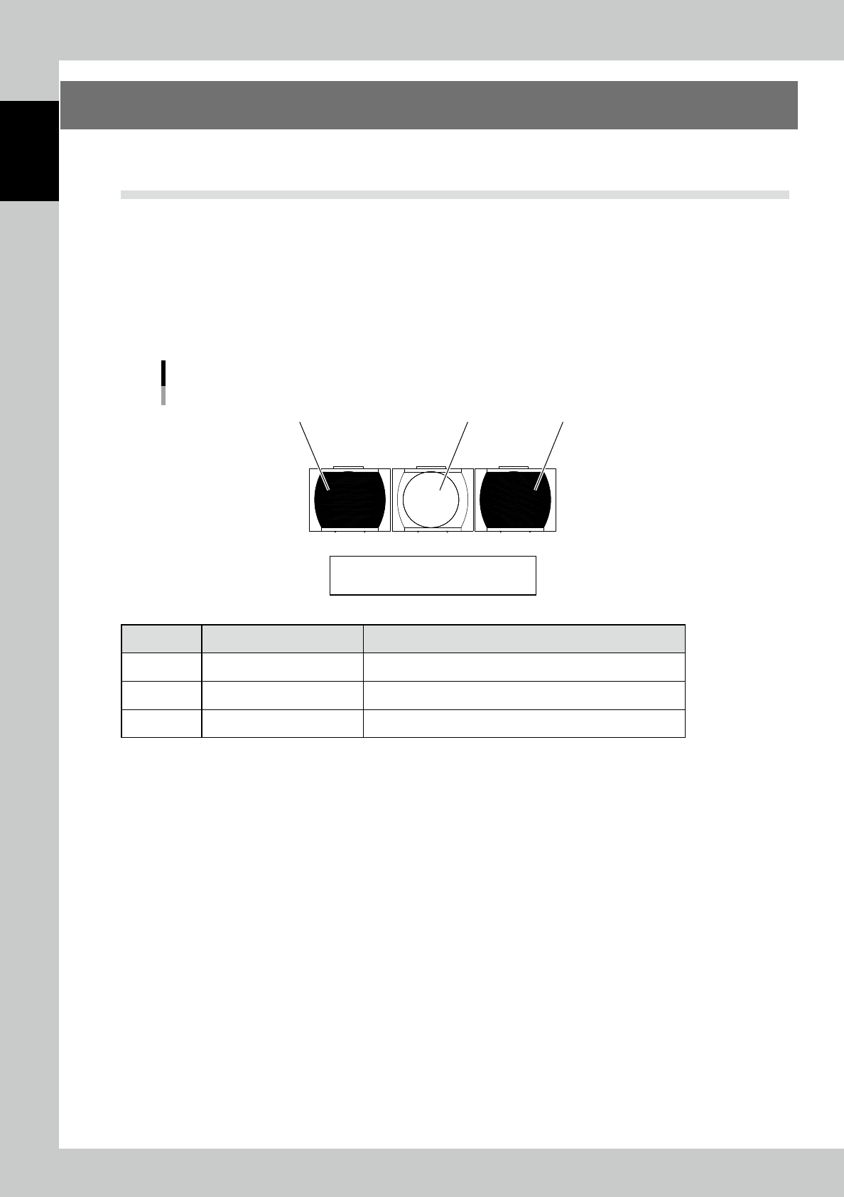
5.1.1 PLC switch panel
The PLC switch panel is located when the keyboard table is opened. It is usually not used. Use the switch
when your personal computer does not operate due to the personal computer failure of machine’s main body.
Switch panel
1
23
Reset / Stop / Start
23106-KMN-00
Machine name Motion and check
1 [Start] button Starts the PASS mode.
2 [Stop] button Stops the PASS mode.
3 [Reset] button Reset the home position.
1-11
1
Overview and maintenance of machine
5.1.2 Adjustment of the conveyor width
Adjustment of conveyor width is done manually in case of personal computer failure.
Insert the conveyor board and adjust to the board width by using the handwheel handle.
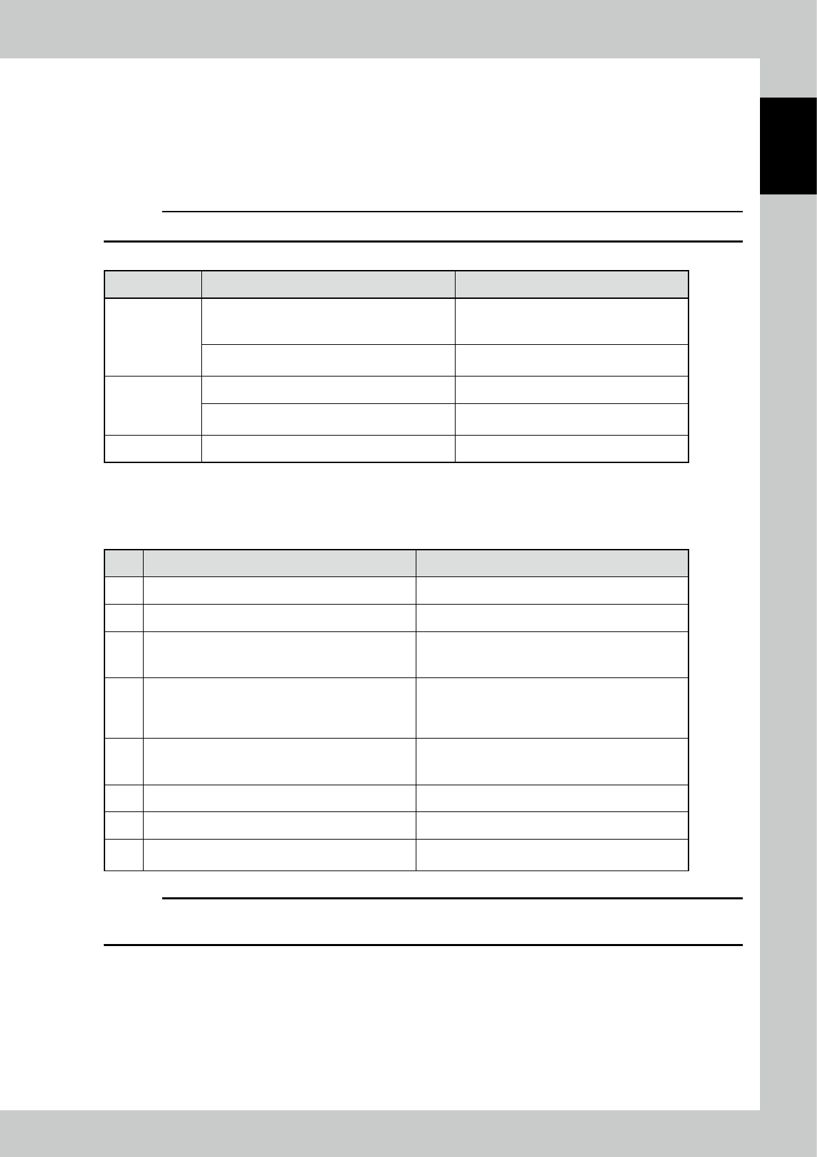
5.1.3 Explanation of switches
c
CAUTION
Switches are enabled only in the forced PASS mode.
Function Motion of the device by the button operation Remarks
[Start] button
When preparation is OFF (the power of the drive
section is OFF), turns on the power of the drive
section.
When the power of the drive section is turned
on, the lamp of the switch blinks.
When preparation is ON (the power of the drive
section is ON), starts the operation of the device.
The lamp of the switch lights up during the
device is in operation.
[Stop] button Stops the operation of the machine.
Starts the forced PASS mode in conjunction with
the breaker of the "primary power."
[Reset] button Resets the error display.
5.1.4 Operational procedure of forced PASS mode
No. Operation or status Motion and check
1 Turn off the breaker of the "primary power."
2 Check the conveyor width. Adjust the conveyor width by the manual wheel.
3
Turn on the breaker of the "primary power" by pressing
and holding the "Stop" button. (Hold the switch for over
three seconds.)
Changes to the PASS mode.
Start of initialization
→
Wait for about three seconds.
4 Press the [Start] button.
Power on of the drive section
→
Wait for about three
seconds.
The switch lamp blinks at the timing of startup is
available.
5 Press the [Start] button.
Starts the automatic operation (PASS mode).
The switch lamp of start lights up.
At this time, check that the tower lights up in "green."
6 By pressing the "Stop" button, the device stops. The switch lamp of start blinks.
7 To operate again, press the "Start" button.
8
For termination, check that boards are ejected, and
then turn off the breaker of the "primary power."
c
CAUTION
If you press the "Emergency stop" button and bring the machine to an emergency stop, release the lock of the
"Emergency stop" button and press the "Reset" button. Then, perform the procedure after the step 4 again.
1-12
1
Overview and maintenance of machine
5.2 Disabling UPS
When UPS battery deteriorates and the voltage drops, PC does not start up or it starts up and shuts down
immediately. The battery replacement for UPS is required, however, the machine can start up by disabling UPS
for a temporary use.
n
NOTE
If disabling UPS, the power supply for PC during power outage is also disabled. Make sure to prepare the maintenance
parts.
n
NOTE
UPS battery is a consumable part. Replacing it every 3 months is recommendable.
1
Power off the machine.
2
Open the door on the lower part of machine.
PC is installed in the machine with the rear faces toward the machine front.
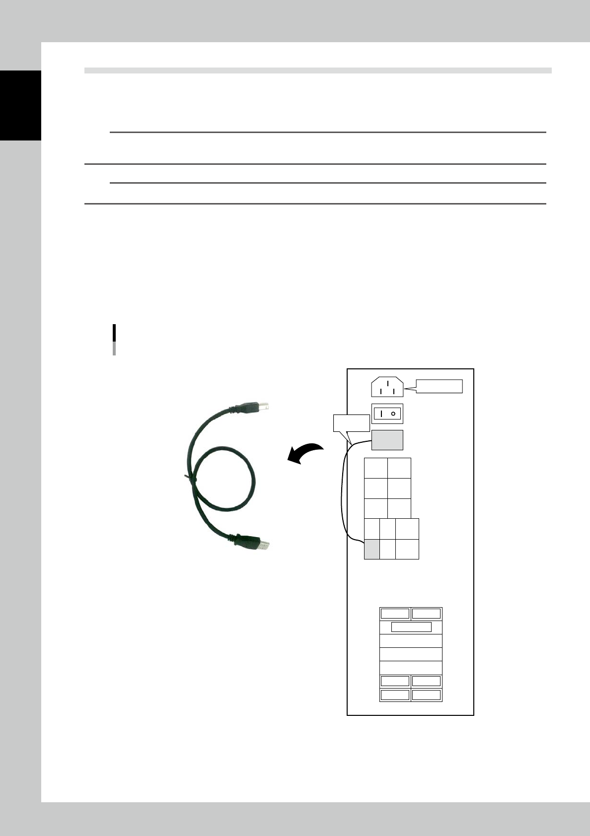
3
Disconnect USB cable.
Disconnect USB cable on the PC rear connecting UPS OUT and UPS IN.
4
Power on the machine.
Disabling UPS
UPS cable
Connection diagram of PC
Power Cable
UPS OUT
USB
USB
NO
USE
NO
USE
NO
USE
NO
USE
NO
USE
LAN
UPS
IN
NO
USE
CN
7104
CN
7111
CN
7125
CN7119
CN7128
NO USE
CN7107
CN7136S
CN7118
CN
7133
Main Power
Accessary
USB Cable
23114-KMN-00