80S-2080F480F4-680F5 User’s Manual.pdf - 第103页
SIPLACE 80S-20/F4/F4-6/F5 User’s Manual 2 Introduction and Basic Concepts Edition 03/98 from S oftware Version SR .404.xx 2.3 Overview of the User Interface and Menu Funct ions 2- 25 2.3.3 Flowch art Option s Menu Fig. 2…
SIPLACE 80S-20/F4/F4-6/F5 User’s Manual 2 Introduction and Basic Concepts
Edition 03/98 from Software Version SR.404.xx 2.3 Overview of the User Interface and Menu Functions
2 - 24
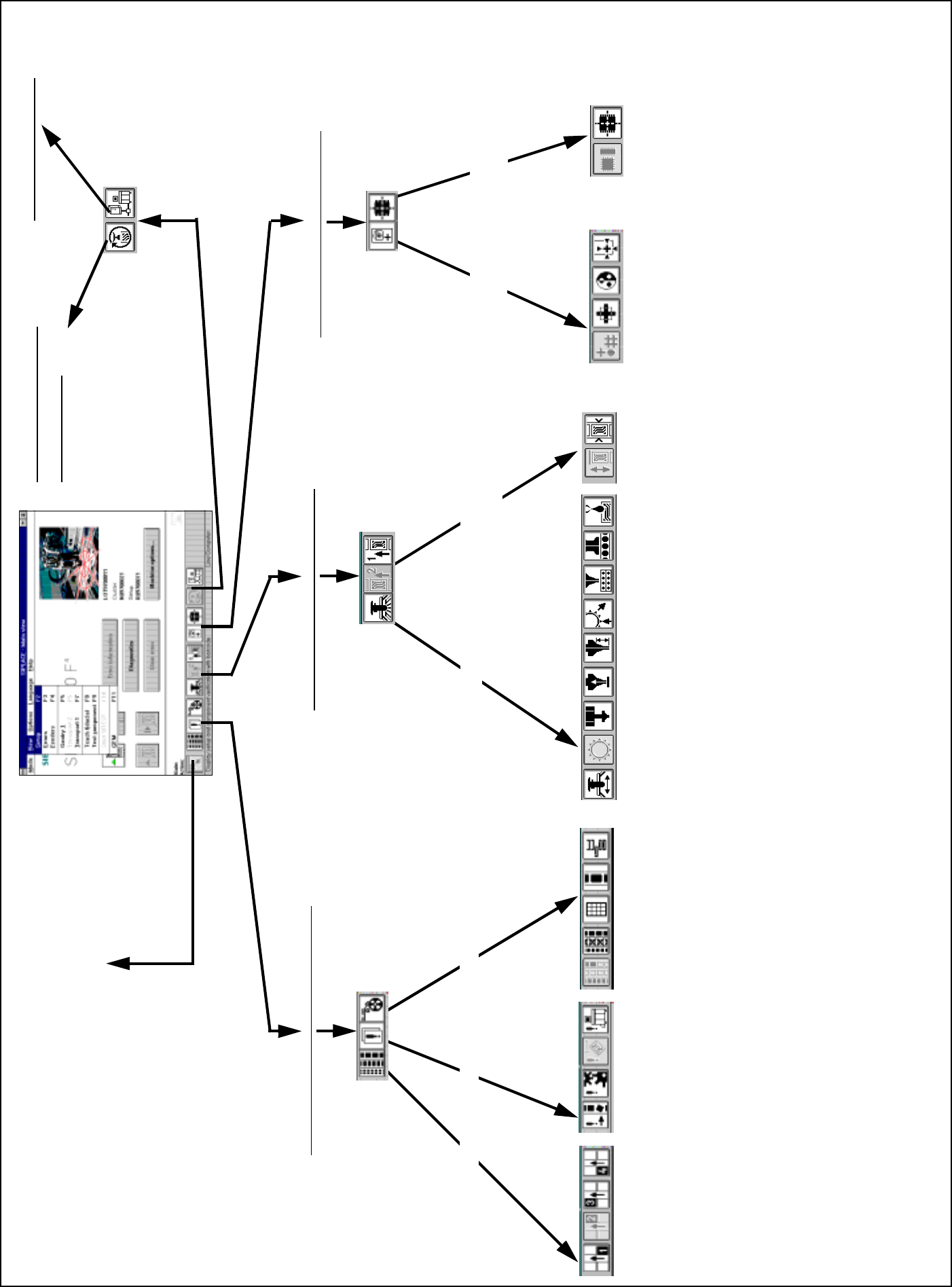
2.3.2 Flowchart “View”
Fig. 2.3.2 Menu “View” flowchart
FeedersErrorsSetup
Placement functions (Chapter 3)
Teach and
test fiducial
Test component and edit
package form data
Vision fuctions (Chapter 5)
GEM (Section11.9)
Back to the Main View
Single functions ( Chapter 4)
Gantry functions PCB Transport 1/2
(2 only available optionally)
Test component
Package form and camera type
Test and center fiducial
Change contrast sensitivity
Teach fiducial, search area and resolution
Select fiducial and gantry
Adjust and measure PCB conveyor width
Transport functions
Fluxing (option)
Nozzle changer configuration IC head
Nozzle changer configuration revolver head
Nozzle configuration revolver head
Nozzle offset revolver head
Vacuum test revolver head
IC-head functions
Revolver head functions
Gantry functions
Functions Wafflepack Changer
Display and vibrate linear feeders
Display trays and inventory levels
Omit components
Display and refill empty tracks
Display all general errors
Display all transport errors
Display all machine errors
Display all track errors
Display setup of location 4
Display setup of location 3
Display setup of location 2
Display setup of location 1
SITEST (see SITEST
User Manual)
SIPLACE 80S-20/F4/F4-6/F5 User’s Manual 2 Introduction and Basic Concepts
Edition 03/98 from Software Version SR.404.xx 2.3 Overview of the User Interface and Menu Functions
2- 25
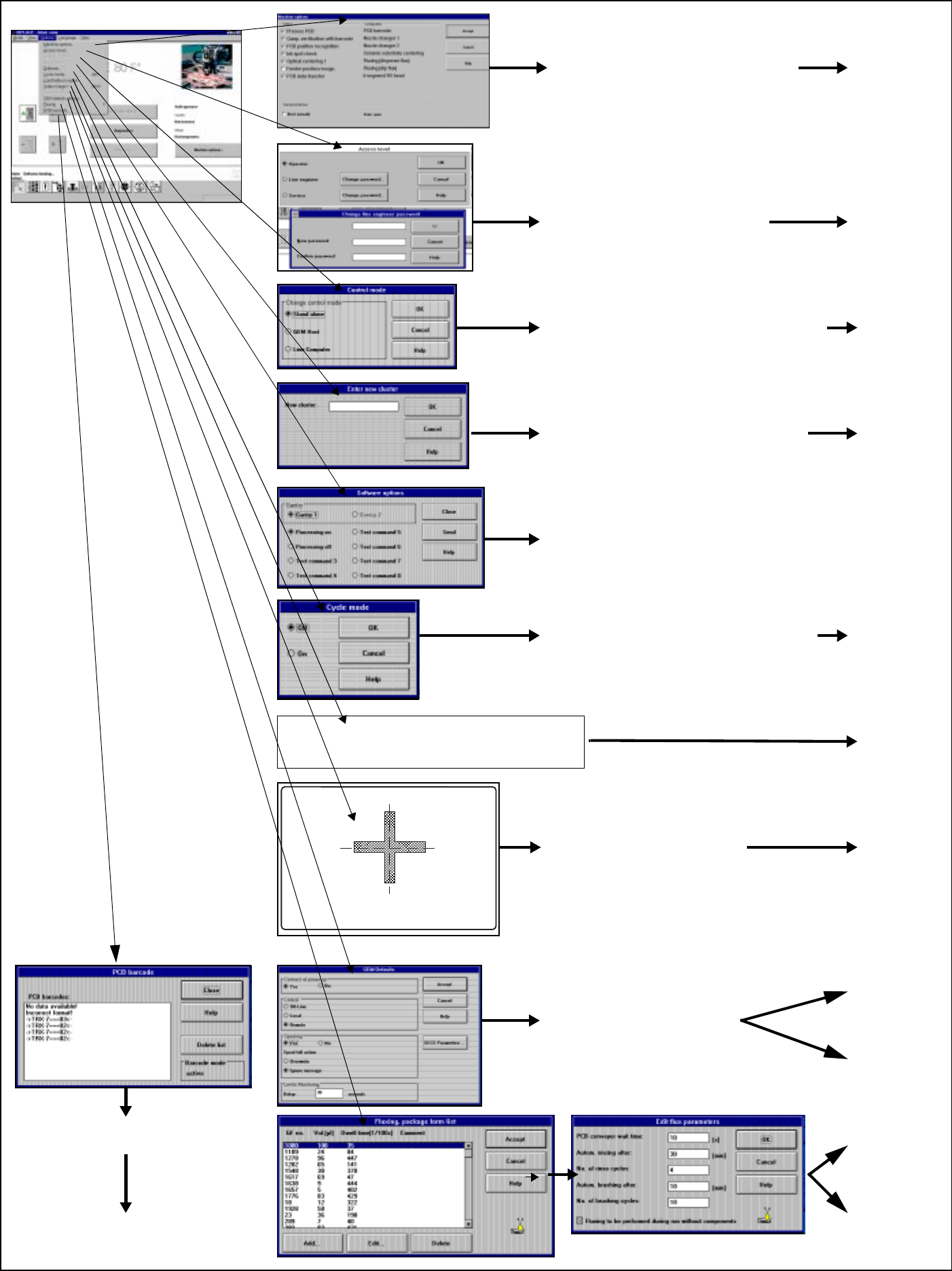
2.3.3 Flowchart Options Menu
Fig. 2.3.3 Flowchart Options menu
See
Section
2.4.4.7
➩ Load table program: Loading the program
for the table program control
➩ The operating mode can be either
Stand-alone (for service purposes only)
or GEM host (only available as an option).
➩ The default is line computer
➩ Displays the configured machine options
➩ Operator can only query
➩ Line engineer can activate / deactivate
➩ Allocate
operator control level and
passwords for
operator, line engineer
or service technician
➩ In Stand-alone operating mode,
a cluster can be loaded from the
hard disk for service purposes
➩ For service technicians only
➩ Cycle mode ON can be activated
in order to localize errors
➩ The start button must be pressed for
every placement step
➩ These are the default
settings for the
GEM option
See
Section
11.9
See
Section
11.7
See
Section
2.4.4.8
See
Section
2.4.4.6
See
Section
2.4.4.3
See
Section
2.4.4.4
See
Section
2.4.4.2
See
Section
2.4.4.1
➩ Switching to the camera
image of the MVS system
(vision evaluation unit)
➩ Press the ESC key to exit
➩ Displays any barcodes
read incorrectly, etc
See
Section 2.4.4.11
See
Section
2.4.4.9
See
Section
2.4.4.10
SIPLACE 80S-20/F4/F4-6/F5 User’s Manual 2 Introduction and Basic Concepts
Edition 03/98 from Software Version SR.404.xx 2.4 Brief Description and Principles of the User Interface
2 - 27
2.4 Brief Description and Principles of the
User Interface
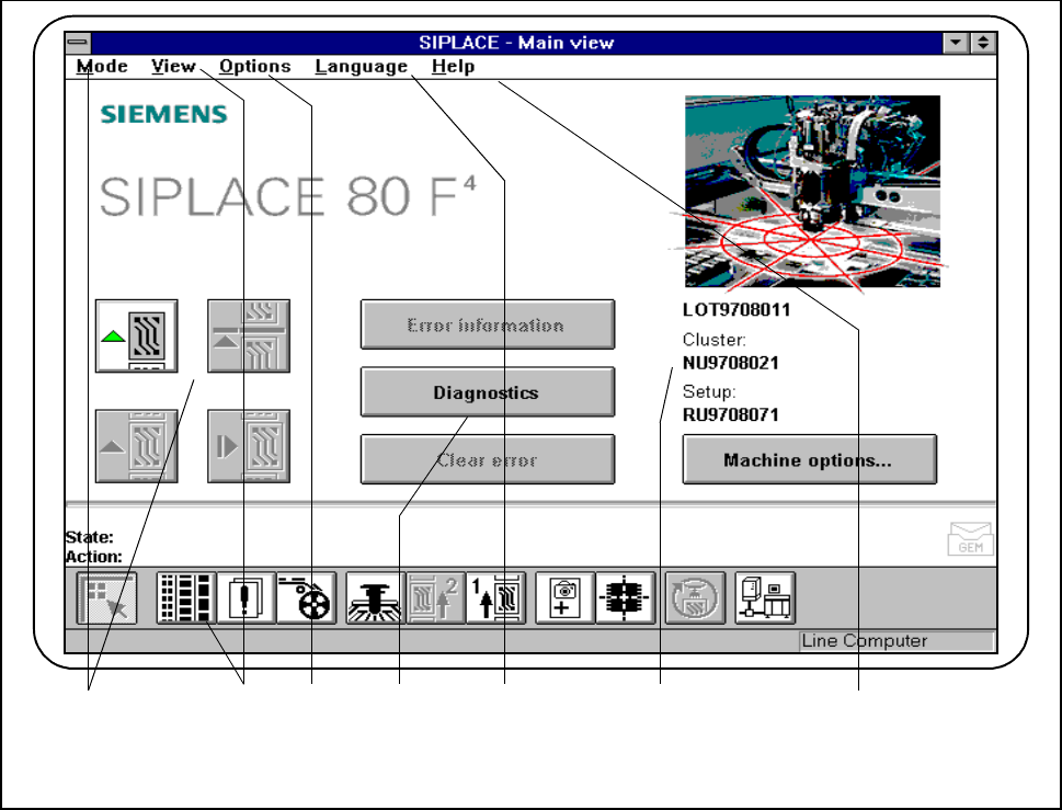
2.4.1 Main View
The main view displays to the operator operating states, central settings and options of the machine. From the
main view the operator can control the basic functions of the machine (see Fig. 2.4.1). Central settings, func-
tions and options can be processed or implemented, depending on the user’s authorization level. You can
return directly to the main view from any other view.
Fig. 2.4.1 Main view
- Key to Fig. 2.4.1
1 The Mode menu 2 The View menu with button bar
3 The Options menu 4 Troubleshooting and Diagnostics buttons
5 The Language menu 6 Display box
7 The Help menu
1 3 2 54 6
7