80S-2080F480F4-680F5 User’s Manual.pdf - 第234页
SIPLACE 80S-20/F4/F4-6/F5 User’s Manual 5 Vision Functi ons Edition 03/98 from S oftware Version SR.404.xx 5.1 Overview of the Vision Sy stems in the SIPLACE 80S-20/F4/F4-6/F5 Mac hines Line engi neer 5 - 13 Fig. 5.1.10 …
5 Vision Functions SIPLACE 80S-20/F4/F4-6/F5 User’s Manual
5.1 Overview of the Vision Systems in the SIPLACE 80S-20/F4/F4-6/F5 Machines Edition 03/98 from Software Version SR.404.xx
5 - 12 Line engineer
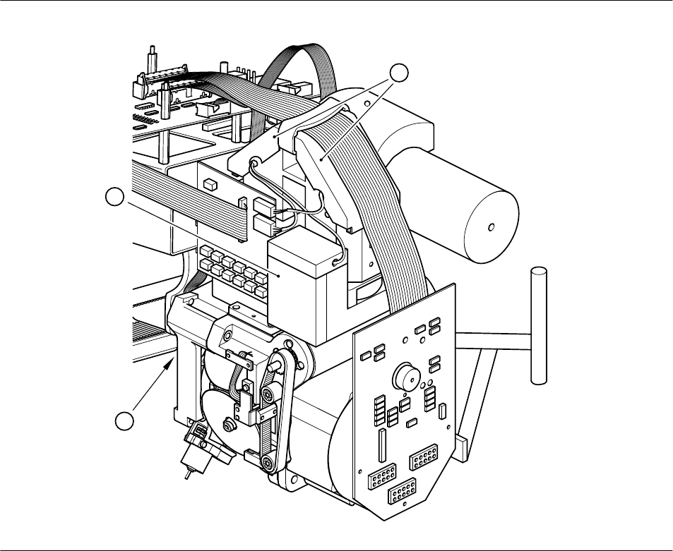
Fig. 5.1.9 Camera systems for PCB and component position recognition at the 6x revolver head of the 80F
4
-6 placement machines
- Key to Fig. 5.1.9
1 Deflection mirror and component lens 2 Component camera
3 PCB camera on the underside of the gantry
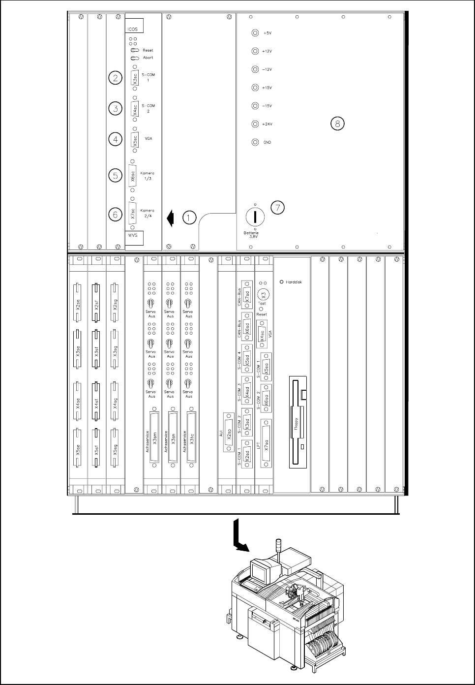
The evaluation unit (ICOS MVS system) which is accommodated in the machine’s control unit (see Fig.
5.1.10, Page 5 - 13) processes and evaluates the signals from the PCB and component camera systems of
the 6x revolver and IC placement heads. The deviations from the nominal values are used for determining
correction values which are then used in the recalculation of the placement positions and the skew of the
components to be inserted.
- Key to Fig. 5.1.10
1 PCB and component evaluation unit of vision system 2 COM1
3 COM2 4 Screen connection
5 Camera connections 6 Camera connections
1 PCB camera 2 IC-head camera
3 Component camera, 6x revolver head 4 FC camera, IC-head
7 Battery 8 Power supply unit
3
1
2
SIPLACE 80S-20/F4/F4-6/F5 User’s Manual 5 Vision Functions
Edition 03/98 from Software Version SR.404.xx 5.1 Overview of the Vision Systems in the SIPLACE 80S-20/F4/F4-6/F5 Machines
Line engineer 5 - 13
Fig. 5.1.10 Vision evaluation unit in the SIPLACE 80F
4
-6 placement machine
5 Vision Functions SIPLACE 80S-20/F4/F4-6/F5 User’s Manual
5.1 Overview of the Vision Systems in the SIPLACE 80S-20/F4/F4-6/F5 Machines Edition 03/98 from Software Version SR.404.xx
5 - 14 Line engineer
5.1.4 Vision Systems in the SIPLACE 80F
5
Placement Machine
The single gantry system of the SIPLACE 80F
5
machine (see Fig. 5.1.11) is fitted with one 6x revolver place-
ment head and one IC placement head. The revolver placement head is equipped with a camera system for
component position recognition (see Fig. 5.1.12, Page 5 - 15). The camera systems (up to two) for compo-
nent position recognition at the IC head are mounted on the machine base (see Fig. 5.1.6, Page 5 - 9).
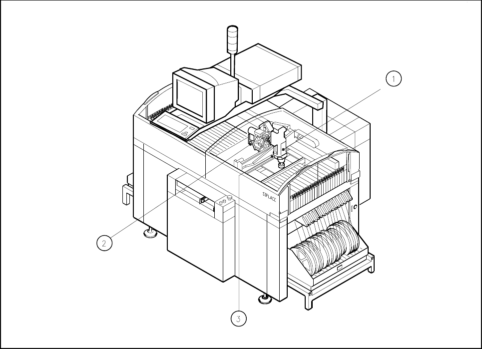
Fig. 5.1.11 Position of the placement heads and of the PCB vision system on the SIPLACE 80F
5
placement machine
- Key to Fig. 5.1.11
1 IC placement head 2 6x revolver placement head
3 PCB camera on the underside of the gantry
Range of components in relation to the placement head and vision system
The following components can be optically centered using the component vision systems and placement
heads developed for the 80F
5
automatic placement systems:
–
6-nozzle revolver head with standard component vision system (see Fig. 5.1.12, Page 5 - 15)
The 6-nozzle revolver head and a standard component vision system can be used to optically center and
insert standard components up to 32mm x 32mm.
–
6-nozzle revolver head with component vision system for flip-chips, bare dies and standard components
(DCA option) (see Fig. 5.1.14, Page 5 - 17)
The 6-nozzle revolver head and a component vision system for flip-chip components, bare dies and stan-
dard components can be used to optically center and insert components up to 13mm x 13mm.
–
IC head
The IC head and IC vision system can be used to visually center and insert components up to 55mm x
55mm in size. The FC vision system can be used to visually center components up to 20 mm x 20 mm
(see Fig. 5.1.6, Page 5 - 9).