80S-2080F480F4-680F5 User’s Manual.pdf - 第238页
SIPLACE 80S-20/F4/F4-6/F5 User’s Manual 5 Vision Functi ons Edition 03/98 from S oftware Version SR.404.xx 5.1 Overview of the Vision Sy stems in the SIPLACE 80S-20/F4/F4-6/F5 Mac hines Line engi neer 5 - 17 Fig. 5.1.14 …
5 Vision Functions SIPLACE 80S-20/F4/F4-6/F5 User’s Manual
5.1 Overview of the Vision Systems in the SIPLACE 80S-20/F4/F4-6/F5 Machines Edition 03/98 from Software Version SR.404.xx
5 - 16 Line engineer
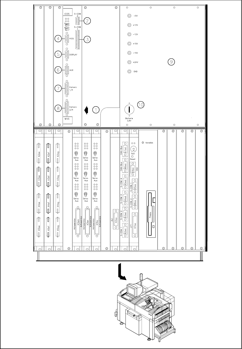
Fig. 5.1.13 Vision evaluation unit in the SIPLACE 80F
5
placement machine
SIPLACE 80S-20/F4/F4-6/F5 User’s Manual 5 Vision Functions
Edition 03/98 from Software Version SR.404.xx 5.1 Overview of the Vision Systems in the SIPLACE 80S-20/F4/F4-6/F5 Machines
Line engineer 5 - 17
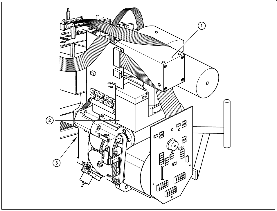
Fig. 5.1.14 Camera systems for PCB and component position recognition at the 6x revolver head
(with with component vision system for flip-chips, bare dies and standard components) of the 80F
5
machines
- Key to Fig. 5.1.14
1 Deflection mirror and component lens 2 Component camera
3 PCB camera on the underside of the gantry
The evaluation unit (ICOS MVS system) which is accommodated in the machine’s control unit (see Fig.
5.1.13, Page 5 - 16) processes and evaluates the signals from the PCB and component camera systems of
the 6x revolver and IC placement heads. The deviations from the nominal values are used for determining
correction values which are then used in the recalculation of the placement positions and the skew of the
components to be inserted.
5 Vision Functions SIPLACE 80S-20/F4/F4-6/F5 User’s Manual
5.1 Overview of the Vision Systems in the SIPLACE 80S-20/F4/F4-6/F5 Machines Edition 03/98 from Software Version SR.404.xx
5 - 18 Line engineer