80S-2080F480F4-680F5 User’s Manual.pdf - 第386页
SIPLACE 80S-20/F4/F4-6/F5 User’s Manual 5 Vision Functi on s Edition 03/98 from S oftware Version SR.404.xx 5.11 Coplanarity Laser M odule (SIPLACE 80F4, 80F4 -6 or 80F5 only) Line engi neer 5 - 165 Fig. 5.11.4 Overview …
5 Vision Functions SIPLACE 80S-20/F4/F4-6/F5 User’s Manual
5.11 Coplanarity Laser Module (SIPLACE 80F4, 80F4 -6 or 80F5 only) Edition 03/98 from Software Version SR.404.xx
5 - 164 Line engineer
DANGER
In the event of any modifications or tampering with the module the factory safety warranty will be rendered null
and void. In addition, the user shall be obliged to comply with the guidelines of the Union of Employers’ Liabil-
ity Insurance Associations [Hauptverband der Berufsgenossenschaften] -VBG 93. In other words:
- Registration with the liability insurance association
- Appointment of a laser safety officer
- Drawing up guidelines for the use of the module
5.11.4 Overview
5.11.4.1 Analysis unit
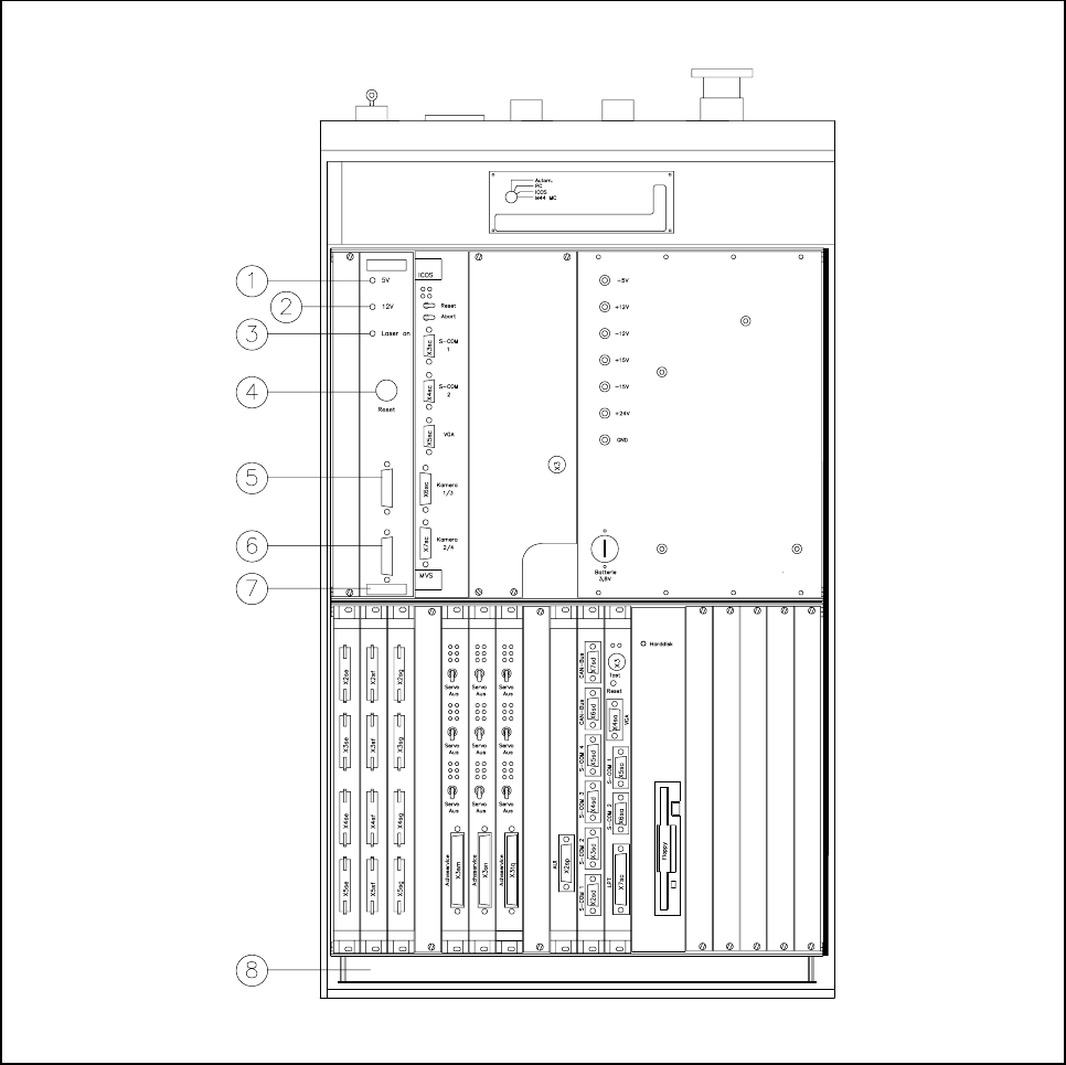
The coplanarity module consists of two components: the analysis unit and control section and the laser
module. The analysis unit is located in the control unit (see Fig. 5.11.4). Three green LEDs on the front panel
of the analysis unit indicate the operating status:
Press the RESET key to initialize the coplanarity module.
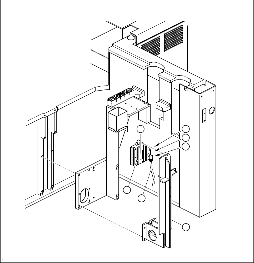
5.11.4.2 Laser module
The laser module is fixed to a supporting frame on the right side of the machine (see Fig. 5.11.5).
Two red LEDs and one green LED signal the operating statuses of the laser module:
LED (see Fig. 5.11.4) On Off
1 green Operating voltage 5V No voltage
2 green Operating voltage 12V No voltage
3 green Laser module in service Laser module switched off
LED (see Fig. 5.11.5) On Off
4 red OUT OF RANGE
(outside the measuring range)
–
5 red POOR TARGET
(components have poor reflection properties)
–
6 green Laser module in service Laser module switched off
SIPLACE 80S-20/F4/F4-6/F5 User’s Manual 5 Vision Functions
Edition 03/98 from Software Version SR.404.xx 5.11 Coplanarity Laser Module (SIPLACE 80F4, 80F4 -6 or 80F5 only)
Line engineer 5 - 165
Fig. 5.11.4 Overview of the coplanarity laser module
- Key to Fig. 5.11.4
1 Green LED: Operating voltage 5V
2 Green LED: Operating voltage 12V
3 Green LED: Laser module switched on
4 RESET key
5 SUB-D plug, 9-pin, COM2: to the machine controller
6 SUB-D plug, 15-pin: to the laser module
7 Analysis unit with control section
8 Control unit 80F
4
/80F
4
-6
5 Vision Functions SIPLACE 80S-20/F4/F4-6/F5 User’s Manual
5.11 Coplanarity Laser Module (SIPLACE 80F4, 80F4 -6 or 80F5 only) Edition 03/98 from Software Version SR.404.xx
5 - 166 Line engineer
Fig. 5.11.5 Coplanarity laser module
- Key to Fig. 5.11.5
1 Laser module
2 Connecting cable
3 Supporting frame
4 Red LED: OUT OF RANGE
5 Red LED: POOR TARGET
6 Green LED: LASER ON
7 Label ’laser class 3B’, see Fig. 5.11.2
4
5
6
1
2
3
7