80S-2080F480F4-680F5 User’s Manual.pdf - 第476页
SIPLACE 80S-20/F4/F4-6/F5 User’s Manual 9 Maintenance Edition 03/98 from S oftware Version S R.404.xx 9.3 Machine Base 9 - 27 Grease th e two lu brication nipple of the rotary cutter c arriage (s ee Fig. 9.3.4 , page 9 -…
9 Maintenance SIPLACE 80S-20/F4/F4-6/F5 User’s Manual
9.3 Machine Base Edition 03/98 from Software Version SR.404.xx
9 - 26
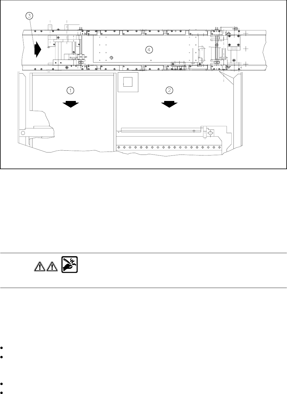
Fig. 9.3.3 Wafflepack changer or component changeover table
- Key to Fig. 9.3.3
1 Wafflepack changer
2 Changeable component table
3 Direction of PCB transport
4 Center conveyor
Checking and replacing the cutter blade and rotary cutter
WARNING
Do not touch the cutting edge of the cutter blade or you risk cutting yourself !
Carry out a visual inspection of the cutter blade and rotary cutter. If the cutting edge is blunt or the cutter blade
in the rotary cutter has worn out, you will need to replace
both
parts each time, as is described in the Compo-
nents table section of the service manual. Setting will be required here.
Cleaning and oiling the guide rail, greasing the rotary cutter carriage
There is a risk of cutting yourself on the cutting edge! Wear sturdy work gloves.
Clean the guide rail (see Fig. 9.3.4, page 9 - 27) with alcohol. In particular remove accumulations of
grease and dirt at either end of the carriage path. Apply some WD40 lubricant and corrosion protection
agent.
To allow you to reach all points, slide the carriage with the rotary cutter by hand.
Use a brush to apply some WD40 lubricant and corrosion protection agent to the rotary cutter and cutter
blade.
SIPLACE 80S-20/F4/F4-6/F5 User’s Manual 9 Maintenance
Edition 03/98 from Software Version SR.404.xx 9.3 Machine Base
9 - 27
Grease the two lubrication nipple of the rotary cutter carriage (see Fig. 9.3.4, page 9 - 27) with a small
quantity of Urethyn E/M2 (approx. 0.5 g + 0.25 g per lubrication nipple). Use the grease gun to do this.
Finally, slide the carriage with the rotary cutter repeatedly back and forth along the guide rail in order to
spread the grease evenly over the lateral guide faces of the guide rail.
Greasing the toothed belt
Use some Staburags N12 to lightly grease the toothed belt for moving the rotary cutter carriage (see Fig.
9.3.4, Page 9 - 27) and the toothed belt for the rotary movement of the rotary cutter (see Fig. 9.3.4, Page
9-27).
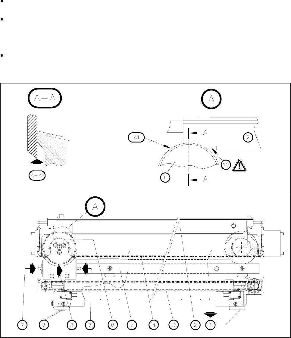
Fig. 9.3.4 Maintenance of the empty tape cutter (the empty tape guide channel has been removed)
- Key to Fig. 9.3.4:
1 Removal of the changeable components table
2 Cutter blade
3 Toothed belt for moving the rotary cutter carriage
4 Toothed belt for the rotary movement of the rotary cutter
5 Guide rail
6 Rotary cutter
7 Lubrication nipple

9 Maintenance SIPLACE 80S-20/F4/F4-6/F5 User’s Manual
9.3 Machine Base Edition 03/98 from Software Version SR.404.xx
9 - 28
8 Rotary cutter carriage in its parking position
9 Compressed air cylinder
10 Cutting edge
A Detail A
A1 Visual inspection: Is the annular face of the rotary cutter blunt?
A-A Section A-A, enlarged view
A-A1 Visual inspection: check the cutting edge.
Risk of injury on the cutting edge!
Refitting the wafflepack changer
NOTE
Every other time the cutter unit is maintained you should also maintain the wafflepack changer.
Re-install the wafflepack changer (see the Component supply section of this user’s manual)
Pay attention to the rotational position of the magazines and the correct assignments of the magazines to
the tray (see Section 9.8, Wafflepack Changer). The position of the wafflepack changer is automatically
recorded following loading of a placement program which includes components being picked up from the
wafflepack changer.
9.3.5 Compressed Air Unit
NOTE
The intervals at which this maintenance work is carried out will depend directly on the quality of the com-
pressed air used. If you fail to meet the quality requirements of the compressed air specification, you should
carry out maintenance more frequently. To prevent contamination in the vacuum circuits of the placement
heads (which is very complicated to remove) you should make sure you change the filter cartridges before
error messages occur.
9.3.5.1 Checking the 5.1 bar Operating Pressure
NOTE
Excessive or inadequate operating pressure will primarily result in vacuum faults, leading to a fatal error mes-
sage and interruption of placement.
For the following work the main switch of the machine is switched on.