80S-2080F480F4-680F5 User’s Manual.pdf - 第477页
9 Maintenance SIPLACE 80S-20/F4/F4-6/F5 User’s Manual 9.3 Machine Base Ed ition 03/98 from Software Version SR.404.xx 9 - 28 8 Rot ary cutt er carri age in its parki ng position 9 Com pressed ai r cyl inder 10 Cutting ed…
SIPLACE 80S-20/F4/F4-6/F5 User’s Manual 9 Maintenance
Edition 03/98 from Software Version SR.404.xx 9.3 Machine Base
9 - 27
Grease the two lubrication nipple of the rotary cutter carriage (see Fig. 9.3.4, page 9 - 27) with a small
quantity of Urethyn E/M2 (approx. 0.5 g + 0.25 g per lubrication nipple). Use the grease gun to do this.
Finally, slide the carriage with the rotary cutter repeatedly back and forth along the guide rail in order to
spread the grease evenly over the lateral guide faces of the guide rail.
Greasing the toothed belt
Use some Staburags N12 to lightly grease the toothed belt for moving the rotary cutter carriage (see Fig.
9.3.4, Page 9 - 27) and the toothed belt for the rotary movement of the rotary cutter (see Fig. 9.3.4, Page
9-27).
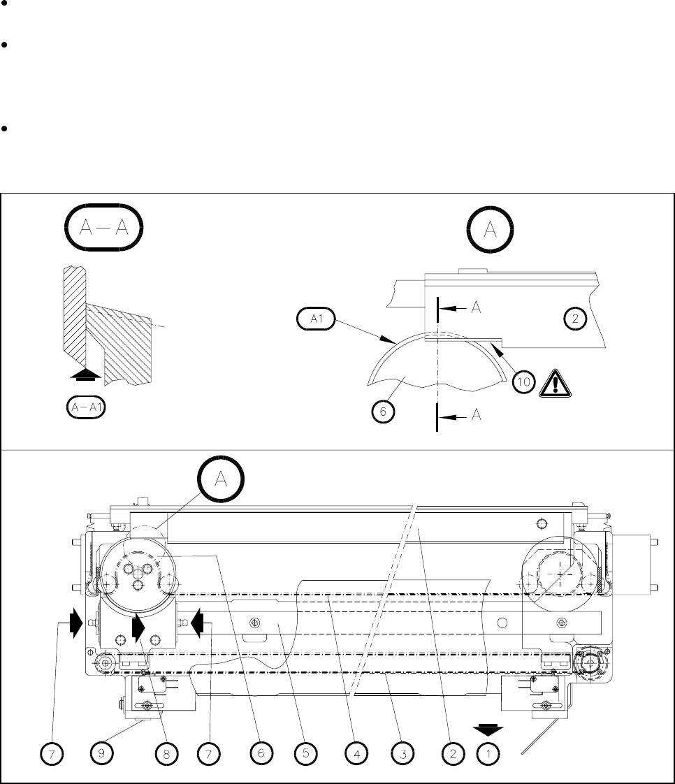
Fig. 9.3.4 Maintenance of the empty tape cutter (the empty tape guide channel has been removed)
- Key to Fig. 9.3.4:
1 Removal of the changeable components table
2 Cutter blade
3 Toothed belt for moving the rotary cutter carriage
4 Toothed belt for the rotary movement of the rotary cutter
5 Guide rail
6 Rotary cutter
7 Lubrication nipple

9 Maintenance SIPLACE 80S-20/F4/F4-6/F5 User’s Manual
9.3 Machine Base Edition 03/98 from Software Version SR.404.xx
9 - 28
8 Rotary cutter carriage in its parking position
9 Compressed air cylinder
10 Cutting edge
A Detail A
A1 Visual inspection: Is the annular face of the rotary cutter blunt?
A-A Section A-A, enlarged view
A-A1 Visual inspection: check the cutting edge.
Risk of injury on the cutting edge!
Refitting the wafflepack changer
NOTE
Every other time the cutter unit is maintained you should also maintain the wafflepack changer.
Re-install the wafflepack changer (see the Component supply section of this user’s manual)
Pay attention to the rotational position of the magazines and the correct assignments of the magazines to
the tray (see Section 9.8, Wafflepack Changer). The position of the wafflepack changer is automatically
recorded following loading of a placement program which includes components being picked up from the
wafflepack changer.
9.3.5 Compressed Air Unit
NOTE
The intervals at which this maintenance work is carried out will depend directly on the quality of the com-
pressed air used. If you fail to meet the quality requirements of the compressed air specification, you should
carry out maintenance more frequently. To prevent contamination in the vacuum circuits of the placement
heads (which is very complicated to remove) you should make sure you change the filter cartridges before
error messages occur.
9.3.5.1 Checking the 5.1 bar Operating Pressure
NOTE
Excessive or inadequate operating pressure will primarily result in vacuum faults, leading to a fatal error mes-
sage and interruption of placement.
For the following work the main switch of the machine is switched on.
SIPLACE 80S-20/F4/F4-6/F5 User’s Manual 9 Maintenance
Edition 03/98 from Software Version SR.404.xx 9.3 Machine Base
9 - 29
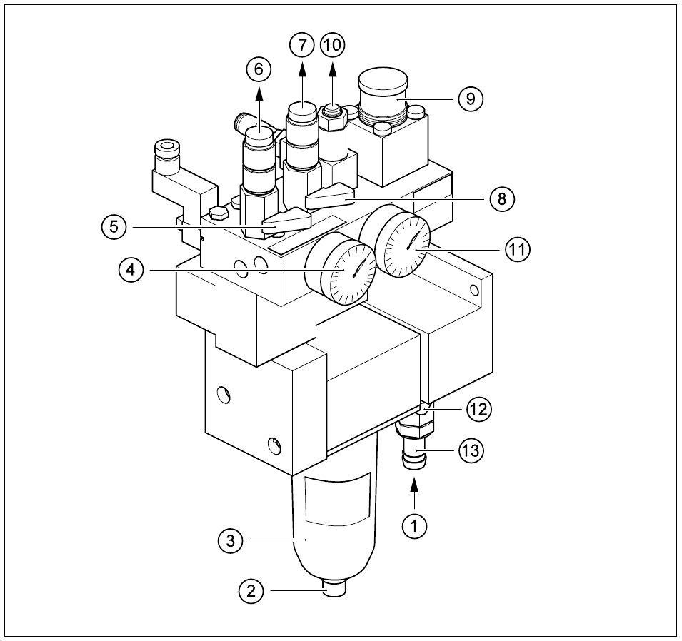
Fig. 9.3.5 Maintenance of the compressed air unit SIPLACE 80S-20, 80F
4
, 80F
4
-6, 80F
5
- Key to Fig. 9.3.5
1 Infeed of the compressed air supply
2 Drain plug for condensate
3 Filter cup, water trap
4 Manometer for operating pressure, 5.0 - 5.3 bar permissible range, permanently set to 5.1 bar
5 Stop valve for compressed air supply, placement head 1, in CLOSED position
6 Compressed air supply for vacuum generation, placement head 1
7 Compressed air supply for vacuum generation, placement head 2
8 Stop valve for compressed air supply, placement head 2, in CLOSED position
9 Compressed air regulator for the stopper
10 Connection for the components table pneumatics system
11 Manometer for compressed air supply to the stopper, 2.3 bar
12 Stop valve of the compressed air supply, in CLOSED position
13 ½“ hose connector with hose clamp