80S-2080F480F4-680F5 User’s Manual.pdf - 第339页
5 Vision Functions SIPLACE 80S-20/F4/F4-6/F5 User’s Manual 5.6 Test Component Edition 03/98 from Software Version SR.404.xx 5 - 118 Line engine er Windows – Separate ly for eac h lead Here you define the window in the pr…
SIPLACE 80S-20/F4/F4-6/F5 User’s Manual 5 Vision Functions
Edition 03/98 from Software Version SR.404.xx 5.6 Test Component
Line engineer 5 - 117
Angle measurement
For single-row components, the angle of rotation is not calculated correctly. Consequently it is better to
access calculation of the angle of rotation in Row measuring mode. Switch off the angle measurement in this
option.
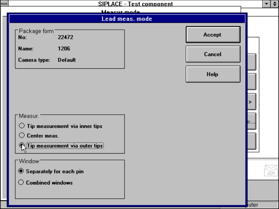
5.6.4.19 ‘Lead’ measuring mode
Click on the ‘Setting’ field in the ‘Lead’ measuring mode to call up the Lead measuring mode menu.
Fig. 5.6.31 Measuring mode option, Lead measuring mode menu
This menu is used to
– specify the lead measuring method.
– to select the windows separately for each lead or a combined window for every lead to be measured.
Measurement
If the inner lead tips are mapped better than the outer tips, for example if a shiny lead is bent upwards slightly,
you can select one of the following options:
– measuring the tips via the inner tips of the leads, for bases, for example
– center of the lead, center measurement, for PLCC, SOJ, for example
– measuring the tips via the outer tips of the leads, for QFP, SOT, SO, for example
5 Vision Functions SIPLACE 80S-20/F4/F4-6/F5 User’s Manual
5.6 Test Component Edition 03/98 from Software Version SR.404.xx
5 - 118 Line engineer
Windows
–
Separately for each lead
Here you define the window in the primary direction (dark blue) and secondary direction (light blue) for
measuring each lead for irregular components and special components.
–
Combined window
Used to define a common window for all the leads.
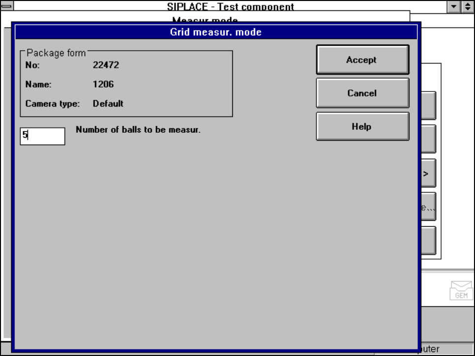
5.6.4.20 ‘Grid’ measuring mode
Click on the ‘Setting’ field in the ‘Grid’ measuring mode to call up the Grid measuring mode menu.
Fig. 5.6.32 Measuring mode option, Grid measuring mode menu
In this menu, enter the number of balls to be measured at each corner.
SIPLACE 80S-20/F4/F4-6/F5 User’s Manual 5 Vision Functions
Edition 03/98 from Software Version SR.404.xx 5.6 Test Component
Line engineer 5 - 119
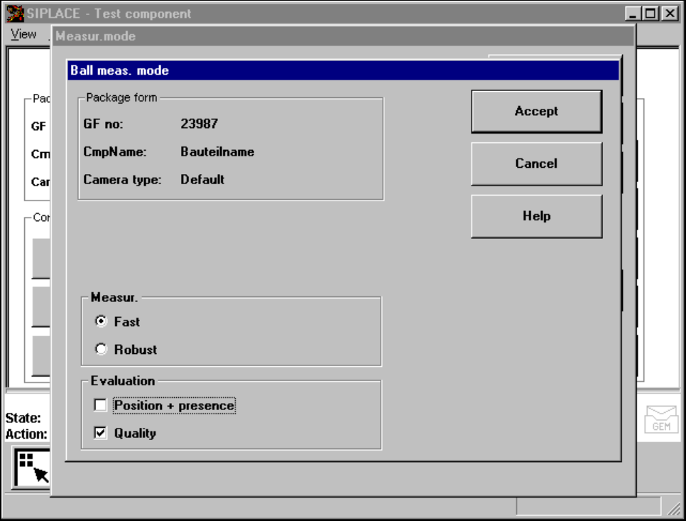
5.6.4.21 ’Ball’ measuring mode
Click on the ’Settings’ button in ’Ball’ measuring mode to call up the ’’Ball measuring mode“ menu.
Fig. 5.6.33 ’Measuring mode’ option, ’’Ball measuring mode“ menu
This menu can be used to
– select the measuring methods listed under ’Measurement’ and
– evaluate the position and presence of balls and carry out a quality analysis.
Measurement
You can choose between the following measuring methods:
– the profile method for fast analysis or
– the filter method for a more robust measuring method, although this will take longer.
The ’fast’ measuring method is generally sufficient. However, we recommend the ’robust’ measuring method if
the quality is insufficient, for example if the quality factor is less than 50.
Analysis
This is used to analyze the position of the balls and to determine whether they are present. It can also be used
to determine the quality of the measurement. The quality of the measurement should generally be better than
50.