80S-2080F480F4-680F5 User’s Manual.pdf - 第538页
SIPLACE 80S-20/F4/F4-6/F5 User’s Manual 9 Maintenance Edition 03/98 from S oftware Version SR.404.xx 9.7 6x Revolver Head (80 00) 9 - 89 9.7.6.3 Replacing the safety O-ring on the valve plunger Spare pa rt O-ring 3 x 1, …
9 Maintenance SIPLACE 80S-20/F4/F4-6/F5 User’s Manual
9.7 6x Revolver Head (8000) Edition 03/98 from Software Version SR.404.xx
9 - 88
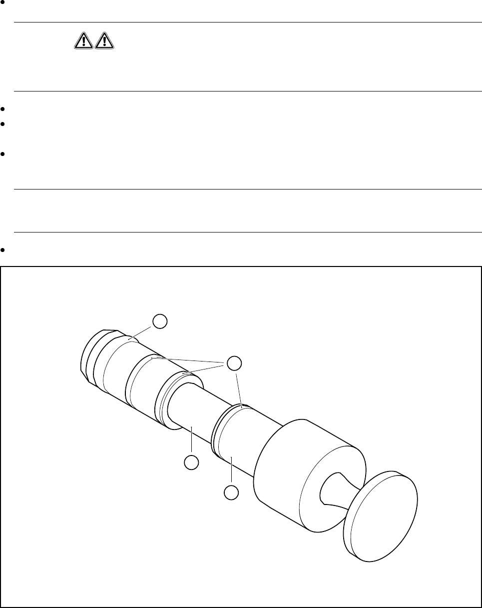
Clean the valve plunger
1
(see Fig. 9.7.10) using a dry, clean cloth.
WARNING
Never use alcohol, cleaning agents or solvents to clean the valve plungers. Cleaning the o-rings using
these agents can result in malfunctions during placement operation (due to vacuum problems).
In particular, ensure that the recess 2 (see Fig. 9.7.10) of the valve plunger is free of grease.
Using a little ISOFLEX® TOPAS® NCA52 grease on a lint-free cloth, lightly grease the o-rings 3 and the
Viton o-ring 4. Make sure that some of the grease is also applied to the recess.
Push the valve plunger 3 (see Fig. 9.7.9, page 9 - 87) back into the valve casing 2 (see Fig. 9.7.9, page
9 - 87) until it reaches the stop.
In particular ensure that the plunger is not skewed when inserted, since this could damage the hole in the
valve casing.
Finally carry out a vacuum test.
Fig. 9.7.10 Cleaning and greasing the valve plunger on the 6x head
- Key to Fig. 9.7.10
1 Valve plunger 2 Recess must be free of grease
3 Lightly grease o-ring and recess 4 Viton o-ring 3x1 (black)
1
2
3
4

SIPLACE 80S-20/F4/F4-6/F5 User’s Manual 9 Maintenance
Edition 03/98 from Software Version SR.404.xx 9.7 6x Revolver Head (8000)
9 - 89
9.7.6.3 Replacing the safety O-ring on the valve plunger
Spare part
O-ring 3 x 1, V70 G200 V, black, from item no. 00336543-01
Equipment
Pointed tweezers, watchmaker’s screwdriver
Remove the valve plunger as described in Section 9.7.6.1 on page 9 - 86.
Use the pointed tweezers or a small watchmaker’s screwdriver to lift the damaged safety O-ring (see item
4 in Fig. 9.7.10, page 9 - 88) out of the groove and remove the O-ring.
Insert the new O-ring.
Clean and grease the valve plunger and insert it again as described in Section 9.5.6.2 on page 9 - 57.
Carry out a vacuum test.

9 Maintenance SIPLACE 80S-20/F4/F4-6/F5 User’s Manual
9.7 6x Revolver Head (8000) Edition 03/98 from Software Version SR.404.xx
9 - 90
9.7.6.4 Error Messages that Suggest that the Valves are Moving Too Freely
The following error messages can appear during the reference run because the valves are moving too freely.
The following error messages can appear during placement because the valves are moving too freely.
When rejecting components
During pick-up or placement operation of components:
Depending on the step motor movement you have to differentiate between two cases:
1. Error messages prompted during a step motor movement inbetween 0° and 90°: The valve plunger will be
moved, the vacuum will be switched on or off.
2. Error message prompted during a step motor movement inbetween 90° and 180°:
The valve plunger has been moved, the step motor drive approaches home position.
NOTE
Error message no. 2327 is also prompted if the step motor movement is faulty inbetween 0° and 90°.
9.7.7 6x Revolver Head Nozzle Survey
The nozzles setting instructions for the 6-nozzle revolver head are given in section 17.2.3 of these operating
instructions.
Error number Error message
2311 Valve adjustment drive pickup/placement cannot be initialized
2313 Valve adjustment drive rejection cannot be initialized
Tab. 9.7.1 Error messages prompted during referencing
Error number Error message
2297 SP: Stepping motor for reject defective
Tab. 9.7.2 Error message prompted during placement operation if components are rejected
Error number Error message
2331 SP: Fault in pick-up/place valve actuator during pick-up
2334 SP: Fault in pick-up/place valve actuator during placement
Tab. 9.7.3 Error messages prompted during pick-up/placement operation with the step motor moving inbetween 0° and 90°
Error number Error message
2327 Star can’t be turned due to pick-up/place valve actuator
Tab. 9.7.4 Error message prompted during pick-up/placement operation with the step motor moving inbetween 90° and 180°