80S-2080F480F4-680F5 User’s Manual.pdf - 第402页
SIPLACE 80S- 20/F4/F4-6/F5 User’s Manual 6 What should you do ... ? Edition 03/98 from S oftware Version S R.404.xx 6.5 When you, a s an operator, ca rry out a walk-round inspection 6 - 11 With waff lepack cha ngers, c h…
6 What should you do ... ? SIPLACE 80S-20/F4/F4-6/F5 User’s Manual
6.5 When you, as an operator, carry out a walk-round inspection Edition 03/98 from Software Version SR.404.xx
6 - 10
6.5 When you, as an operator, carry out a walk-round
inspection
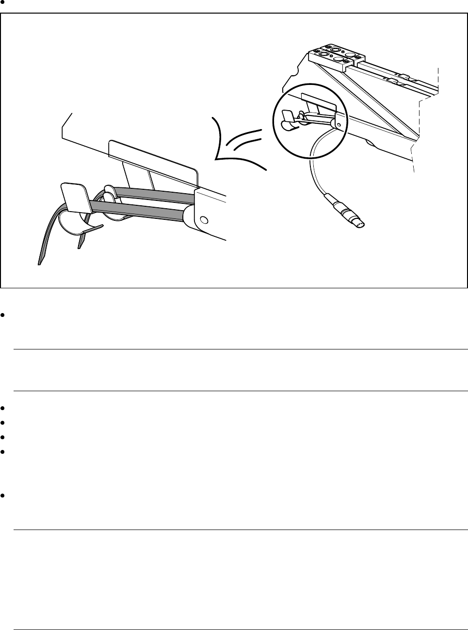
Check that the tape is lying correctly in the springs of the 8 mm S.
Fig. 6.5.1 Placing the tape in the springs of the 8 mm S
Check whether the tape cover foil container for the 8 mm S is full. If it is, pull out the foil and cut it off with
scissors.
PLEASE NOTE:
If you tear the foil, this can lead to tape removal problems.
Check whether the window on the feeder module is the right size for the component.
Are the tape guides used on the feeder modules intended for different tape widths?
Is the additional plastic guide in use for tapes of different widths?
Check the position of the stopper on the PCB transport.
Always position the stopper centrally, outside the PCB. Make sure that the stopper is also positioned out-
side any recesses in the PCB.
Check the magnetic supports on the lifting table. They must be arranged so that they do not collide with
components on the bottom of the PCBs.
PLEASE NOTE:
Splice the tapes in good time so that the feeder modules will not run out of tape, since this will increase
the frequency of stoppages.
However, do not splice the tapes too early since, if you wind the end of the old tape onto the new reel after
splicing, the reel holding the new tape will be overfilled and the tapes will slip off the reel and become tan-
gled up. This will again result in pick-up errors and more stoppages.
In preparation
SIPLACE 80S-20/F4/F4-6/F5 User’s Manual 6 What should you do ... ?
Edition 03/98 from Software Version SR.404.xx 6.5 When you, as an operator, carry out a walk-round inspection
6 - 11
With wafflepack changers, check that the trays with the wafflepacks lie against the guides and are firmly
held in place by the magnets. Do not forget to check the polarity of the components in the tray.
Prepare the used tape reels for the feeder modules.
For heavy tape reels, insert shafts into the tape container.
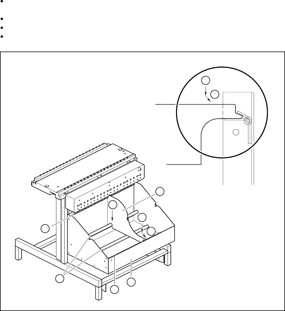
Insert the dividing plates as shown in Fig. 6.5.2 and remember that the smallest division of the tape con-
tainer is a 2x division. This will avoid placement errors.
Fig. 6.5.2 Inserting dividing plates into the containers
Key to Fig. 6.5.2
1 Tape container
2 Dividing plate
3 Guide rail for the dividing plates on the front of the container
4 Guide rail for the dividing plates on the back of the container
5 Supporting rod for the dividing plates
Steps for Fig. 6.5.2
A Insert the dividing plate with the nose under the guide rail on the front of the container.
B Push the dividing plate in direction (B).
C Engage the dividing plate on the supporting rod (5)
4
5
3
1
2
C
A
B
A
B

6 What should you do ... ? SIPLACE 80S-20/F4/F4-6/F5 User’s Manual
6.6 When you carry out a preliminary set-up Edition 03/98 from Software Version SR.404.xx
6 - 12
6.6 When you carry out a preliminary set-up
Use this checklist when you carry out the preliminary set-up on the machine.
Clean the feeder modules with a vacuum cleaner or by "shaking them out".
Remove the cover foil from the S feeder modules.
Clean the supporting surfaces of the feeder modules.
Clean the component tables
Use a vacuum cleaner or a short-bristled brush to remove loose components on the component table.
RISK OF INJURY
Avoid removing components from the magnetic rail of the component table with your fingers because you may
hurt yourself with tiny splinters of metal. Use a brush instead.
Abrade the magnetic rail of the component table with the oilstone on a regular basis - or if you detect irreg-
ularities (see Section 9.3.3 ’Component Tables’, page 9 - 20).
Clean the contact surfaces on the bottom of the component table.
Clean the tape container with a vacuum cleaner.
Check that the feeder modules are divided up correctly.
Check the feeder module location.
Are all the plugs of the feeder module plugged in at the correct places?
Shorten the used tape at the front of the feeder module to around 3 cm.
Are the tape container plates inserted correctly (see Fig. 6.5.2, page 6 - 11)?
Check the size of the component reel and equip large reels with shafts.
Splice short tape ends together.
Personnel in the preliminary set-up area should have access to the same equipment as the machine opera-
tors. A list of equipment is given in Section 6.13 on page 6 - 21.
PLEASE NOTE:
If the equipment is defective, the machine operator should inform (in writing or orally) the personnel in the pre-
liminary set-up area.