80S-2080F480F4-680F5 User’s Manual.pdf - 第607页
11 Station Extensions/Options SIPLACE 80S-20/F4/F4-6/F5 User’s M anual 11.2 Nozzle Changer for IC Head (ICP W20) Edition 03/98 from S oftware Version SR.404.xx 11 - 10 11.2.2 Technical Data 11.2.3 How It Works Fig. 11.2.…
SIPLACE 80S-20/F4/F4-6/F5 User’s Manual 11 Station Extensions/Options
Edition 03/98 from Software Version SR.404.xx 11.2 Nozzle Changer for IC Head (ICPW20)
11 - 9
11.2 Nozzle Changer for IC Head (ICPW20)
11.2.1 Overview
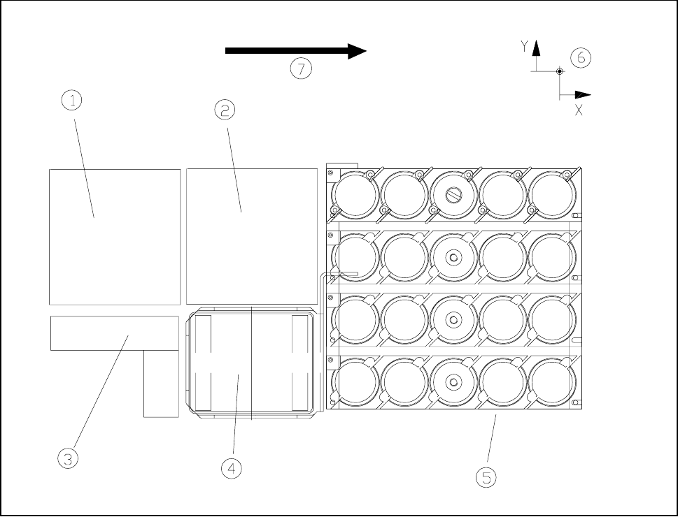
Fig. 11.2.1 Location where the nozzle changer for IC head is installed
- Key to Fig. 11.2.1
1 Component vision camera 2 Location where the flip-chip camera is installed
3 Coplanarity module 4 Reject box
5 Nozzle changer 6 Machine zero point
The nozzle changer is of modular design and consists of at least 1 but at most 4 trays, each with 5 nozzle
garages.
The trays are placed on a shared carrier which is located in the area between the board conveyor and the
feed modules.
The individual trays are fastened to the carrier by means of a countersunk screw in the central nozzle garage.
The precise positioning of the trays with respect to one another is regulated by means of two alignment pins.
11 Station Extensions/Options SIPLACE 80S-20/F4/F4-6/F5 User’s Manual
11.2 Nozzle Changer for IC Head (ICPW20) Edition 03/98 from Software Version SR.404.xx
11 - 10
11.2.2 Technical Data
11.2.3 How It Works
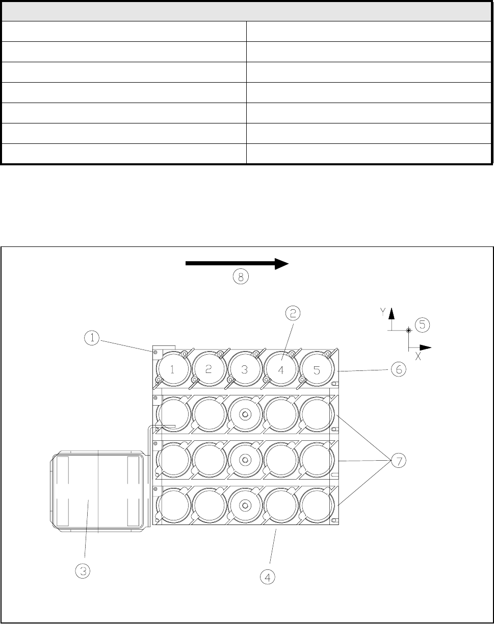
Fig. 11.2.2 Nozzle changer overview
Nozzle changer for IC head
Length 165 mm
Width 160 mm
Height 485 mm
Number of trays min.1 (standard) / max. 4
Number of nozzle garages min. 5 (standard) / max. 20
Usable nozzle types 416, 417, 418, 419
Material Plastic or steel

SIPLACE 80S-20/F4/F4-6/F5 User’s Manual 11 Station Extensions/Options
Edition 03/98 from Software Version SR.404.xx 11.2 Nozzle Changer for IC Head (ICPW20)
11 - 11
- Key to Fig. 11.2.2
1 Position fiducial 2 Nozzle garage
3 Reject box 4 Nozzle changer
5 Machine zero point 6 Tray 1 (standard)
7 Trays 2 to 4 (optional)
- Each of the individual trays bears a position fiducial which is used for position recognition.
- The individual locations in the magazines are numbered consecutively from 1 to 4.
- The individual nozzle garages in the individual magazines are numbered consecutively from 1 to 5.
- The nozzles are held securely in the garages by means of spring-loaded detents. Depending on the direc-
tion in which the IC head axis rotates the nozzles will either be clamped or released.
11.2.4 Notes for Operators and Service Staff
To insert or change nozzles use the nozzle removal tool (see Section 9.6.6 in this user’s manual).
Clean the nozzle changer in the way described in Section 9.3.7 of this user’s manual.