80S-2080F480F4-680F5 User’s Manual.pdf - 第38页
0 Introduction SIPLACE 80S-20/F4/F4-6/F5 User’s Manual 0.4 Overall View of Asse mblies Edition 03/98 from S oftware Version S R.404.xx 0 - 34 0.4.8 Overa ll View of IC Head Fig. 0.4.8 Overall view of IC h ead - Key to Fi…
SIPLACE 80S-20/F4/F4-6/F5 User’s Manual 0 Introduction
Edition 03/98 from Software Version SR.404.xx 0.4 Overall View of Assemblies
0 - 33
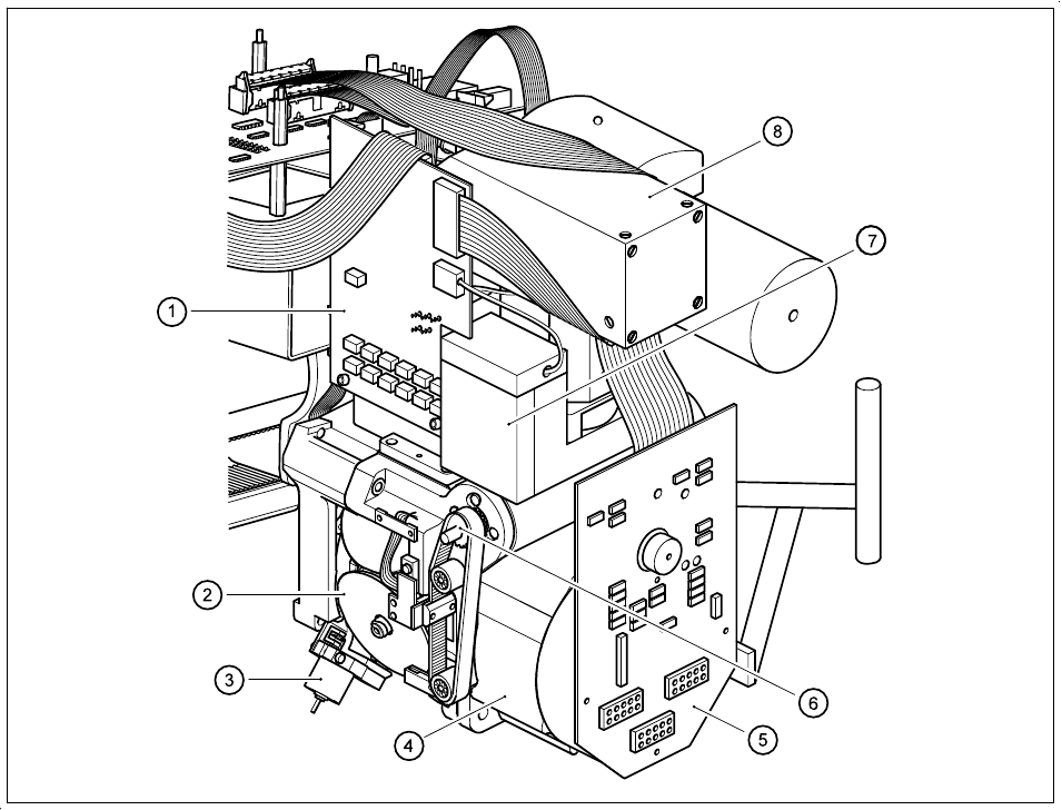
0.4.7 Overview of the 6-nozzle revolver head with component vision
system for flip-chip-components, bare dies and standard compo-
nents (DCA option)
Fig. 0.4.7 Overview of the 6-nozzle revolver head with component camera for flip-chips, bare dies and standard components
(DCA option)
- Key to Fig. 0.4.7
1 Component illumination control board 2 Sleeves (1 to 6)
3 Adjustment unit for reject position 4 Star drive
5 Intermediate distribution board 6 Z axis drive
7 Component camera 8 Component illumination system for flip-chips,
bare dies and standard components (DCA option)
0 Introduction SIPLACE 80S-20/F4/F4-6/F5 User’s Manual
0.4 Overall View of Assemblies Edition 03/98 from Software Version SR.404.xx
0 - 34
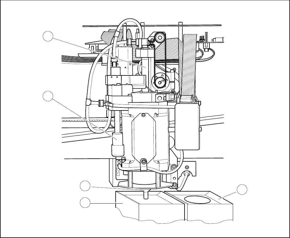
0.4.8 Overall View of IC Head
Fig. 0.4.8 Overall view of IC head
- Key to Fig. 0.4.8
1 Sleeve 2 Vacuum nozzle
3 Nozzle 4 Component vision system
5 Flip-chip vision system
1
2
3
4
5
SIPLACE 80S-20/F4/F4-6/F5 User’s Manual 0 Introduction
Edition 03/98 from Software Version SR.404.xx 0.4 Overall View of Assemblies
0 - 35
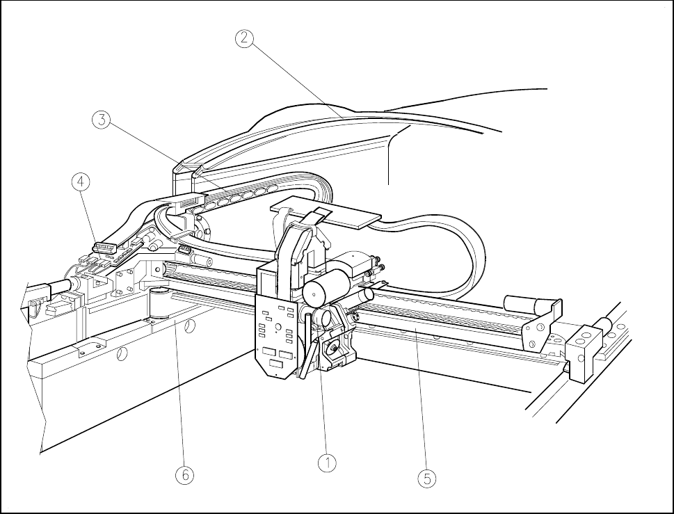
0.4.9 Overall View of the Gantry
Fig. 0.4.9 Overall view of the gantry
- Key to Fig. 0.4.9
1 Revolver head 2 Protective cover
3 Drag cable 4 Gantry axes conversion board
5 X axis 6 Y axis