80S-2080F480F4-680F5 User’s Manual.pdf - 第213页
4 Single Functi ons SIPLACE 80S-20/F4/F4-6 User’s Manual 4.4 Single Functions: Transport 1 Edition 07/97 from Software Version SR.403.xx 4 - 48 4.4. 1.6 Sensor S tate - R efresh When t his func tion is s elected the curr…

SIPLACE 80S-20/F4/F4-6 User’s Manual 4 Single Functions
Edition 07/97 from Software Version SR.403.xx 4.4 Single Functions: Transport 1
4 - 47
4.4.1.2 PCB to Output Conveyor
When this function is selected a board on the center conveyor will be conveyed onwards to the output con-
veyor where it is stopped and clamped.
Within the working area click on the PCB to output conveyor button. A board which is on the center con-
veyor will be conveyed onwards to the station’s output conveyor.
4.4.1.3 Actuate Stopper
When this function is selected the stopper is extended.
Within the working area click on the Actuate stopper button. The stopper will be extended.
If you click on the button once more the stopper will return to its original position.
Further clicking on the button will repeat the sequence.
4.4.1.4 Actuate Clamping
When this function is selected the clamping is activated (if there is a board on the conveyor it will be clamped).
Within the working area click on the Actuate clamping button. Board clamping will be activated.
If you click on the button once more the clamping device will return to its original position.
Further clicking on the button will repeat the sequence.
4.4.1.5 Ceramic Substrate Centering (Option)
When this function is selected ceramic substrate centering is activated (if there is a board on the conveyor it
will be clamped).
Within the working area click on the Ceramic substrate centering button. Clamping will be activated for
ceramic substrate centering.
If you click on the button once more the clamping device will return to its original position.
Further clicking on the button will repeat the sequence.
NOTE
See also Section 11.6 'Ceramic Substrate Centering' in Chapter 11 'Station Extensions/Options'.

4 Single Functions SIPLACE 80S-20/F4/F4-6 User’s Manual
4.4 Single Functions: Transport 1 Edition 07/97 from Software Version SR.403.xx
4 - 48
4.4.1.6 Sensor State - Refresh
When this function is selected the current state of the ultrasonic sensors will be displayed (1 = responded;
0 = not responded). The input conveyor (input), center conveyor (center) and output conveyor (output) are
interrogated.
Within the Sensor state working area click on the Refresh button. The current state of the sensors at the
board conveyor will be displayed in the Sensor state working area.
4.4.1.7 Conveyor - High Speed
With this function the two different speeds of the conveyor belts can be checked and if necessary adjusted at
the half-bridge board in the servo unit. When this function is selected you can specify either a high or a low
speed for the conveyor speed.
NOTE
The belts must be empty.
The input conveyor only travels at high speed.
Click on the High speed check box.
Once the check box has been activated, click on the On button and the conveyor belts will be run at the
higher speed.
If the check box has been deactivated, click on the On button and the conveyor belts will be run at the
lower speed.
SIPLACE 80S-20/F4/F4-6 User’s Manual 4 Single Functions
Edition 07/97 from Software Version SR.403.xx 4.4 Single Functions: Transport 1
4 - 49
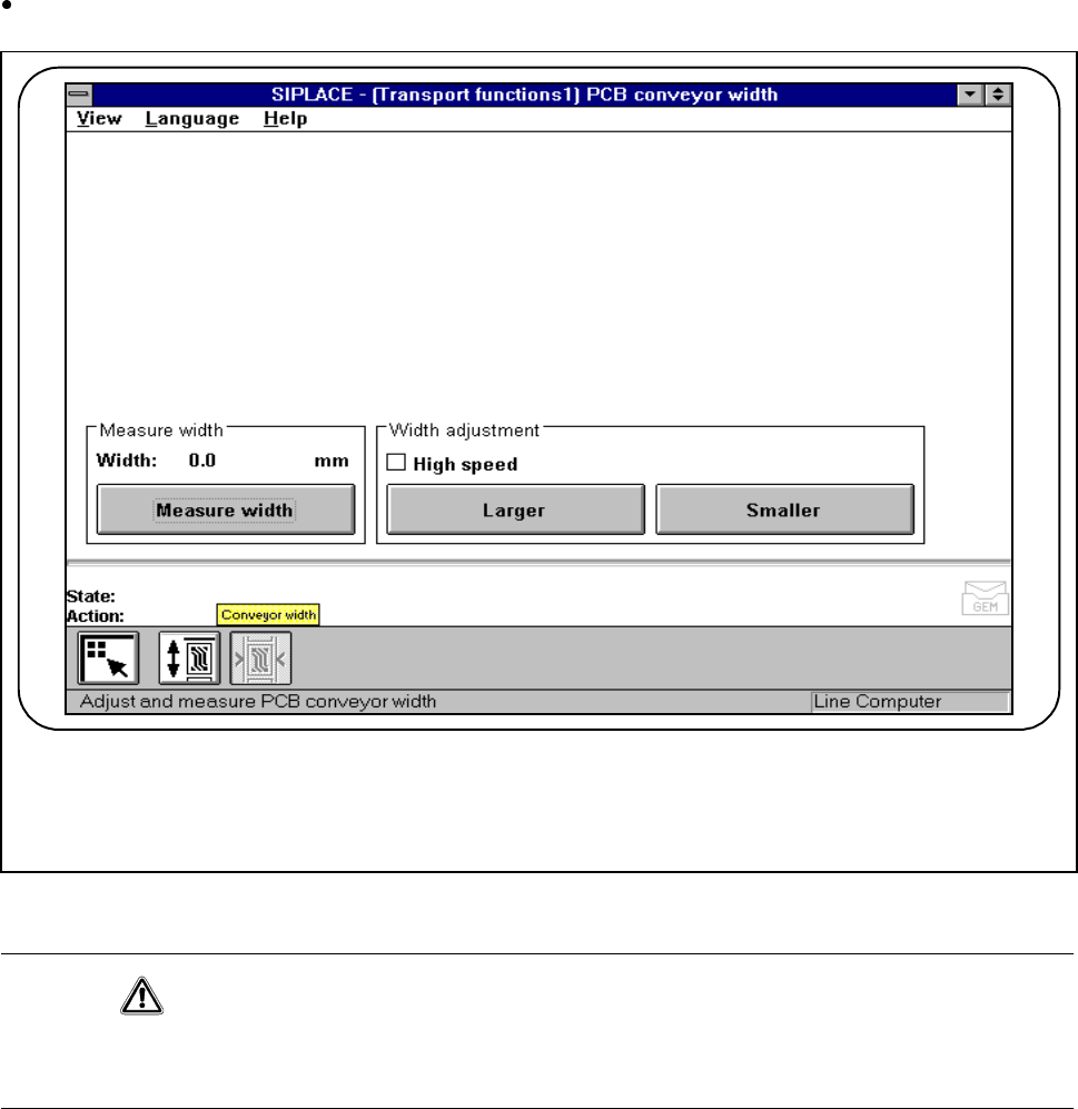
4.4.2 Conveyor Width
It will be necessary to alter the width of the conveyor when a different board size is introduced or during vari-
ous types of maintenance work.
In the PCB transport screen click on the Conveyor width button.
Fig. 4.4.3 Conveyor width
CAUTION
Before adjusting the conveyor width make sure that there are no boards or other objects on the machine’s
conveyors. Failure to do so may result in damage to the machine and board.
4.4.2.1 PCB Transport Width- Measure Width
Within the working area click on the Measure width button . The width of the board conveyor is measured,
displayed and saved.
F