80S-2080F480F4-680F5 User’s Manual.pdf - 第367页
5 Vision Functions SIPLACE 80S-20/F4/F4-6/F5 User’s Manual 5.7 Guidelines for D escribing Package Form s Edition 03/98 from Software Vers ion SR.404.xx 5 - 146 Line engine er 5.7.9.3 S ettings for Illuminating Components…
SIPLACE 80S-20/F4/F4-6/F5 User’s Manual 5 Vision Functions
Edition 03/98 from Software Version SR.404.xx 5.7 Guidelines for Describing Package Forms
Line engineer 5 - 145
Middle illumination level
The middle illumination level can be used universally with a wide range of components. With bright compo-
nent bodies, ceramic components, µBGAs and flip-chips it should, however, only be used at lower intensity
levels.
Steep illumination level
The main application for the steep illumination level is for reflective leads, ceramic components and bright
component bodies. It is less suitable for bare dies, flip-chips or µBGAs.
NOTE
Most components will require a combination of these three illumination levels to achieve optimum illumination.
Using
one
illumination level will only be successful in exceptional cases.
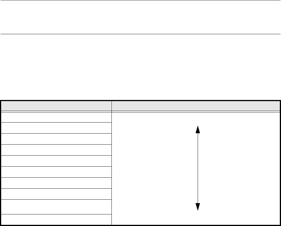
5.7.9.2 Pseudo color representation
The pseudo color representation provides a powerful and objective assessment of the illumination, by repre-
senting a brightness value in a color.
A contrast of at least 4 color scales between the lead and body is required for a measurement. In the ‘Illumina-
tion’ menu of the package form manipulator, components are displayed in the pseudo color representation on
the station computer monitor.
Color scale Brightness
white light
yellow
orange
red
brown
green
light blue
blue
violet
black dark
Tab. 5.7.6 Conversion table for the pseudo color representation at the 6x revolver head
5 Vision Functions SIPLACE 80S-20/F4/F4-6/F5 User’s Manual
5.7 Guidelines for Describing Package Forms Edition 03/98 from Software Version SR.404.xx
5 - 146 Line engineer
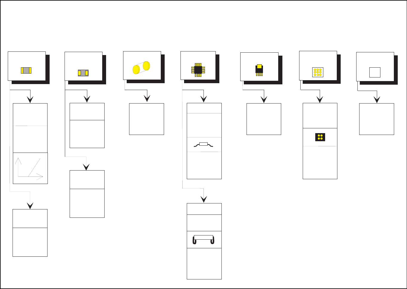
5.7.9.3 Settings for Illuminating Components
The standard range of components includes chips (0402 to 2220), tantalum capacitors, Melf components,
PLCCs, QFPs, SOs, SOJs, TSOPs, ICs, power components, flip-chips, µBGAs, BGAs and bare dies.
For the components which are listed below the GF interpreter in the station computer uses the default illumi-
nation parameters listed in Fig. 5.7.12:
– Chips (0402 to 2220)
– Tantalum capacitors (component bodies, non-reflective)
– Melf
– PLCC, QFP, SO, SOJ, TSOP, ICs, power ICs
– Flip-chips, µBGAs, BGAs
– Bare dies
As a rule you will not need to change the illumination parameters for the components.
SIPLACE 80S-20/F4/F4-6/F5 User’s Manual 5 Vision Functions
Edition 03/98 from Software Version SR.404.xx 5.7 Guidelines for Describing Package Forms
Line engineer 5 - 147
.
Fig. 5.7.12 Illumination Values for standard components at the 6x revolver head camera (DCA option) on the 80 F
5
placement
machine
Adjusting the illum ination of standard com ponents
Chip
IC
Power IC
Melf
BGA, µBG A
flip -c h ip
Tantalum
capacitor
BGA,
µBG A,
flip -c h ip
0805 and
larger
0201,
0402,
0603
G eneral
Reflective
body
X plane: 50
fla t: 5 0
m iddle: 50
s te e p : 5 0
G u llw in g
SO, SOT,
TSO P
QFP,
J-Lead
PLCC
255
150
X plane: 50
fla t: 5 0
m iddle: 50
s te e p : 5 0
X plane: 0
fla t: 5 0
m iddle: 80
s te e p : 1 0 0
X plane: 230
fla t: 2 3 0
m id d le : 2 0
s te e p : 2 0
X plane: 200
fla t: 1 0 0
m id d le : 4 0
s te e p : 4 0
X plane: 0
fla t: 8 0
m iddle: 50
s te e p : 5 0
X plane: 0
fla t: 0
m iddle: 100
s te e p : 2 0
X plane: 150
fla t: 3 0
m id d le : 0
s te e p : 0
Bare Die
X plane: 0
fla t: 8 0
m iddle: 50
s te e p : 5 0
X plane: 0
fla t: 0
m iddle: 50
s te e p : 1 1 0