80S-2080F480F4-680F5 User’s Manual.pdf - 第606页
SIPLACE 80S-20/F4/F4-6/F5 User’s Manual 11 Station Extensions/Options Edition 03/98 from Software Version SR.404.xx 11. 2 Nozzle Changer for IC Head (ICPW20) 11 - 9 11.2 Nozzle Cha nger for IC Head (ICPW20) 11.2.1 Overvi…
11 Station Extensions/Options SIPLACE 80S-20/F4/F4-6/F5 User’s Manual
11.1 Nozzle Changer for the 12x Revolver Head Edition 03/98 from Software Version SR.404.xx
11 - 8
SIPLACE 80S-20/F4/F4-6/F5 User’s Manual 11 Station Extensions/Options
Edition 03/98 from Software Version SR.404.xx 11.2 Nozzle Changer for IC Head (ICPW20)
11 - 9
11.2 Nozzle Changer for IC Head (ICPW20)
11.2.1 Overview
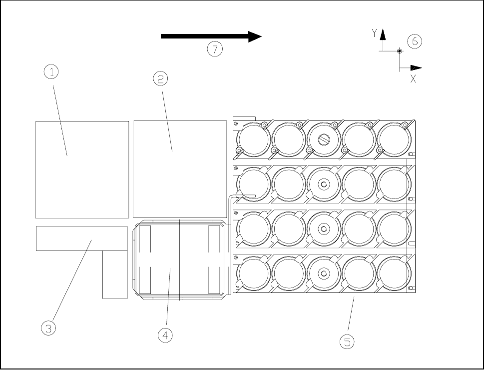
Fig. 11.2.1 Location where the nozzle changer for IC head is installed
- Key to Fig. 11.2.1
1 Component vision camera 2 Location where the flip-chip camera is installed
3 Coplanarity module 4 Reject box
5 Nozzle changer 6 Machine zero point
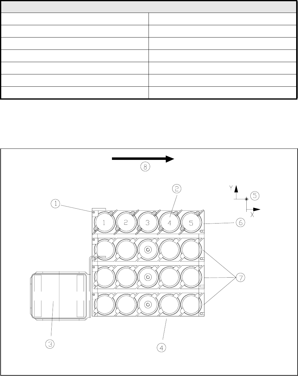
The nozzle changer is of modular design and consists of at least 1 but at most 4 trays, each with 5 nozzle
garages.
The trays are placed on a shared carrier which is located in the area between the board conveyor and the
feed modules.
The individual trays are fastened to the carrier by means of a countersunk screw in the central nozzle garage.
The precise positioning of the trays with respect to one another is regulated by means of two alignment pins.
11 Station Extensions/Options SIPLACE 80S-20/F4/F4-6/F5 User’s Manual
11.2 Nozzle Changer for IC Head (ICPW20) Edition 03/98 from Software Version SR.404.xx
11 - 10
11.2.2 Technical Data
11.2.3 How It Works
Fig. 11.2.2 Nozzle changer overview
Nozzle changer for IC head
Length 165 mm
Width 160 mm
Height 485 mm
Number of trays min.1 (standard) / max. 4
Number of nozzle garages min. 5 (standard) / max. 20
Usable nozzle types 416, 417, 418, 419
Material Plastic or steel