80S-2080F480F4-680F5 User’s Manual.pdf - 第377页
5 Vision Functions SIPLACE 80S-20/F4/F4-6/F5 User’s Manual 5.9 Teach Fiducial: Additions with the 80F4, 80F4-6 or 80F5 Machines Ed ition 03/98 from Software Version SR.404.xx 5 - 156 Line engine er
SIPLACE 80S-20/F4/F4-6/F5 User’s Manual 5 Vision Functions
Edition 03/98 from Software Version SR.404.xx 5.9 Teach Fiducial: Additions with the 80F4, 80F4-6 or 80F5 Machines
Line engineer 5 - 155
5.9
Teach Fiducial
: Additions with the 80F
4
, 80F
4
-6 or
80F
5
Machines
In contrast to the 80S-20 placement machine the 80F
4
, 80F
4
-6 or 80F
5
machine is a single-gantry machine.
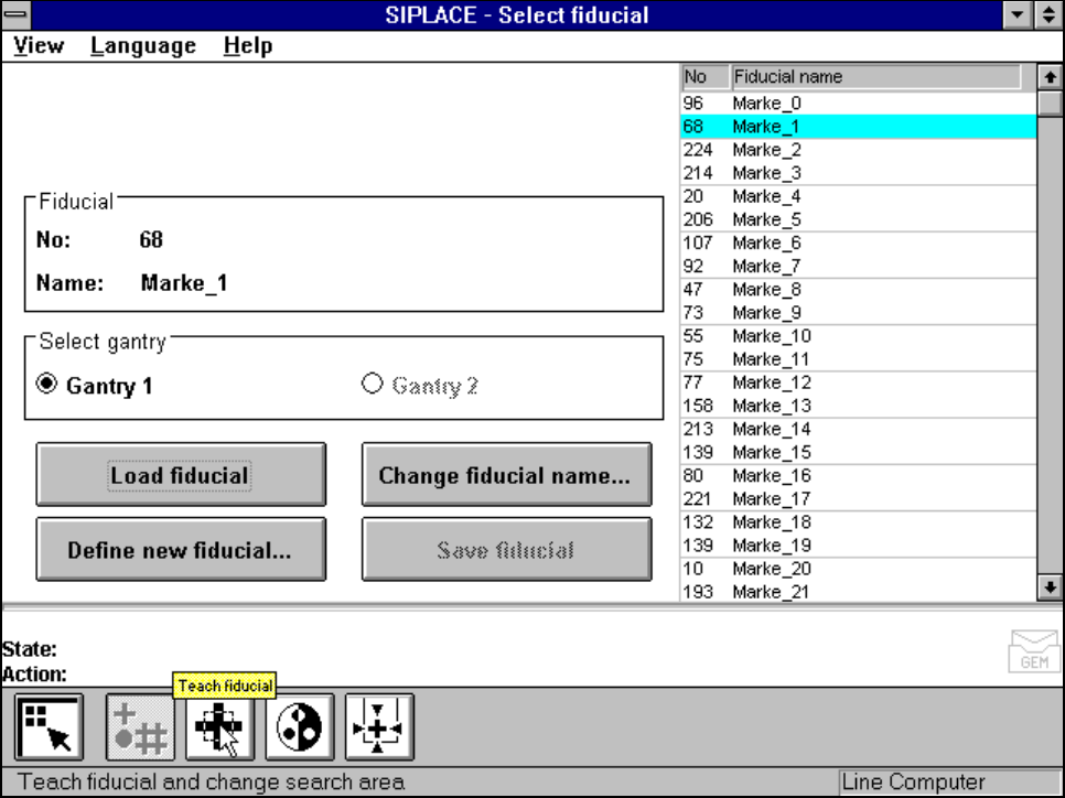
For this reason in the Teach fiducial menu the Select gantry option is permanently set to Gantry 1. The
Gantry 2 option cannot be clicked on.
The IC placement head is mounted on the gantry, together with the 12x revolver placement head on the 80F
4
and the 6x revolver placement head on the 80F
4
-6 and 80F
5
automatic placement machines. The camera
system for board centering is accommodated on the gantry underside.
All menus with the exception of this option are identical to those of the 80S-20 machine.
A description of the menus and their options will be found in Section 5.5 from Page 5 - 43.
Fig. 5.9.1 Select fiducial menu, Select gantry option
5 Vision Functions SIPLACE 80S-20/F4/F4-6/F5 User’s Manual
5.9 Teach Fiducial: Additions with the 80F4, 80F4-6 or 80F5 Machines Edition 03/98 from Software Version SR.404.xx
5 - 156 Line engineer
SIPLACE 80S-20/F4/F4-6/F5 User’s Manual 5 Vision Functions
Edition 03/98 from Software Version SR.404.xx 5.10 Test Component: Supplements to the 80F4, 80F4-6 or 80F5 Machines
Line engineer 5 - 157
5.10
Test Component
: Supplements to the 80F
4
, 80F
4
-6
or 80F
5
Machines
On the 80F
4
, 80F
4
-6 or 80F
5
automatic placement machines, you can optically center fine-pitch components
with a maximum edge length of up to 55 mm with the IC camera. Components with an edge length exceeding
32 mm, multiple measurement is employed. In addition, you can also optically center BGAs using the IC sen-
sor.
Multiple measurement will be launched each time you access the Measure component or Test component
options.
The following conditions apply to multiple measurement:
1. The number of measurements to be carried out will be determined by the MVS system using a particular
algorithm. The component size and tolerance values will, for example, be input into this algorithm.
2. In the MVS system the combination of different measurement methods will be specified. You will not be
able to change the combination of methods nor the hex parameters.
With the FC camera you can optically center fine-pitch components and flip-chips.
As regards information on and definitions of BGAs, flip-chips and their measurement methods see Section
5.6.4.4, Page 5 - 88.
For information on the ball model description see Section 5.6.4.11 from Page 5 - 104.
In the Measuring mode menu (see Section 5.6.4.13, Page 5 - 106), you can select and activate different
measuring methods and modify the associated measuring parameter values.
Safety information on the component vision systems of the 80F
4
, 80F
4
-6 or 80F
5
machines
DANGER
You must not make any modifications whatsoever to or tamper with the safety features of the 80F
4
, 80F
4
-6 or
80F
5
machines or the IC or flip-chip modules.
The optical range of the IC and flip-chip camera conforms to laser class 1, provided that the camera is perma-
nently fixed in the automatic placement system and that the protective covers are closed (EN 60825-1 and
IEC 825).
Fig. 5.10.1 Identification label for Laser class 1
s