80S-2080F480F4-680F5 User’s Manual.pdf - 第388页
SIPLACE 80S-20/F4/F4-6/F5 User’s Manual 5 Vision Functi on s Edition 03/98 from S oftware Version SR.404.xx 5.11 Coplanarity Laser M odule (SIPLACE 80F4, 80F4 -6 or 80F5 only) Line engi neer 5 - 167 5.11.5 Entering Data …
5 Vision Functions SIPLACE 80S-20/F4/F4-6/F5 User’s Manual
5.11 Coplanarity Laser Module (SIPLACE 80F4, 80F4 -6 or 80F5 only) Edition 03/98 from Software Version SR.404.xx
5 - 166 Line engineer
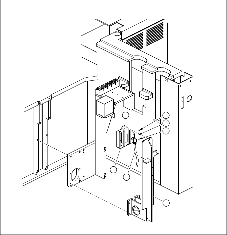
Fig. 5.11.5 Coplanarity laser module
- Key to Fig. 5.11.5
1 Laser module
2 Connecting cable
3 Supporting frame
4 Red LED: OUT OF RANGE
5 Red LED: POOR TARGET
6 Green LED: LASER ON
7 Label ’laser class 3B’, see Fig. 5.11.2
4
5
6
1
2
3
7

SIPLACE 80S-20/F4/F4-6/F5 User’s Manual 5 Vision Functions
Edition 03/98 from Software Version SR.404.xx 5.11 Coplanarity Laser Module (SIPLACE 80F4, 80F4 -6 or 80F5 only)
Line engineer 5 - 167
5.11.5 Entering Data
– Coplanarity measurement must have been added, via the GF editor, to the Handling rules. (See Section
5.4.4 of the SIPLACE UNIX line computer user’s manual).
– Add the maximum coplanarity deviation (see Max. component height tolerance in Section 5.2.5 Func-
tion of the Cluster Editor of the SIPLACE UNIX line computer user’s manual).
NOTE
In the Placement options menu (see Section 5.3 of this user’s manual) you can deactivate or activate the
coplanarity laser module. Coplanarity measurement can be switched on or off for all of those components for
which coplanarity measurement has been set in the package form data.
r
5 Vision Functions SIPLACE 80S-20/F4/F4-6/F5 User’s Manual
5.11 Coplanarity Laser Module (SIPLACE 80F4, 80F4 -6 or 80F5 only) Edition 03/98 from Software Version SR.404.xx
5 - 168 Line engineer