80S-2080F480F4-680F5 User’s Manual.pdf - 第27页
SIPLACE 80S-20/F4/F4-6/F5 User’s Manual 0 Introduction Edition 03/98 from S oftware Version SR.404.xx 0.2 Technical Data 0 - 23 0.2.4.5 Boards, Components, Tapes 0.2.4.6 Connection and Installation Data 0.2.4.7 Machine D…
0 Introduction SIPLACE 80S-20/F4/F4-6/F5 User’s Manual
0.2 Technical Data Edition 03/98 from Software Version SR.404.xx
0 - 22
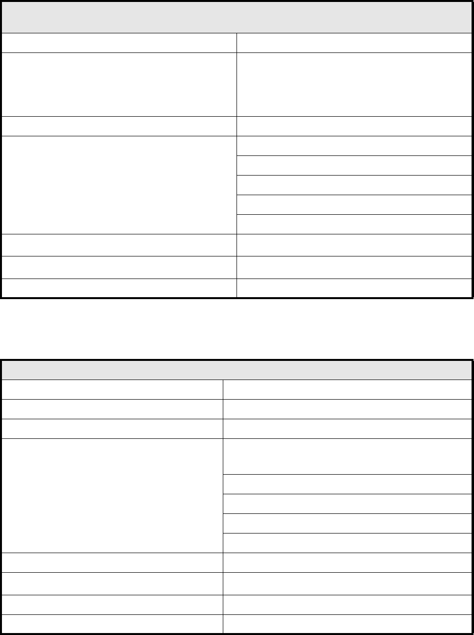
0.2.4.3 6-nozzle revolver head (with component vision system for flip-chips,
bare dies and standard components, DCA option)
0.2.4.4 IC Placement Head
6-nozzle revolver head (with component vision system for flip-chips, bare dies and standard
components, DCA option)
Programmable placement force (z axis) 2.0 N to 5.0 N
Nozzle types
24 (70x, 71x, 72x, 75x, 8xx)
PLEASE NOTE:
Only type 75x nozzles may be used
for inserting flip-chips and bare dies.
Segments 6
Components that can be assembled
Max. height 6.0 mm
Min. pitch 0.2 mm
Minimum ball diameter 110 µm
Dimensions: 0.25 mm x 0.5 mm to 13 mm x 13 mm
Weight up to 5 grams
Resolution dp turning axes
0.0125
o
Resolution star axis
0.0025
o
Stroke z axis Max. 16 mm
IC placement head
Number 1
Nozzle types 4 (4xx)
Component centering Fine-pitch vision module
Components that can be assembled
Max. height:
PCB
thickness
+ PCB
warpage
+ Comp.
height
≤ 14 mm
Min. pitch 0.4 mm
Min. height 0.3 mm
Dimensions: up to 55 mm x 55 mm (larger on request )
Weight up to 25 grams
Max. component height with pneumatic cutter 14 mm (from 12 to 72 mm tapes only)
Resolution of d axis
0.005
o
Stroke z axis Max. 50 mm
Programmable placement force (z axis) 1.0 to 10 N
SIPLACE 80S-20/F4/F4-6/F5 User’s Manual 0 Introduction
Edition 03/98 from Software Version SR.404.xx 0.2 Technical Data
0 - 23
0.2.4.5 Boards, Components, Tapes
0.2.4.6 Connection and Installation Data
0.2.4.7 Machine Dimensions
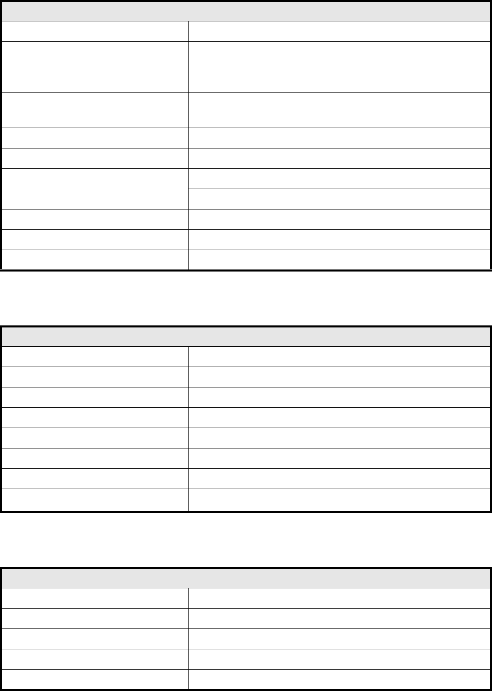
Boards, components, tapes
Boards (PCB) transport system In-line transport with width adjustment
PCB format
50 mm x 50 mm to 460 mm x 460 mm with PCB buffer
50 mm x 50 mm to 508 mm x 460 mm without PCB buffer
(on request)
Component-free guide edge
of the board
3 mm
Min. PCB thickness 0.5 mm
Max. PCB thickness 4.5 mm
Max. PCB warpage
Upwards: 4.5 mm less PCB thickness
Downwards: 0.5 mm plus the PCB thickness
PCB change time 2.5 sec.
Max. number of 8 mm tapes 80
Tape reel diameter Max. 15“ in the reel container
Connection and installation data
System voltage 230/400 V ± 10 % (50/60 Hz)
System voltage (option for USA) 110/208 V ± 10 % (50/60 Hz)
Total connected load 5 kVA
Total power consumption 5 kW
Fuse protection 3 x 16 A
Compressed air supply Min. 5.5 bar / max. 10 bar
Entire compressed air consumption 250 NL/min.
Machine footprint
Permissible surface load > 1000 kg/m
2
Machine dimensions
Weight base module 1500 kg
Weight fully-equipped Approx. 2000 kg
Length 1587 mm
Width 2425 mm
Height with warning light 1836 mm
0 Introduction SIPLACE 80S-20/F4/F4-6/F5 User’s Manual
0.2 Technical Data Edition 03/98 from Software Version SR.404.xx
0 - 24
0.2.4.8 Permissible Environmental Influences
0.2.4.9 Machine control
0.2.4.10 Compressed Air Specification
0.2.4.11 Noise Emission Values
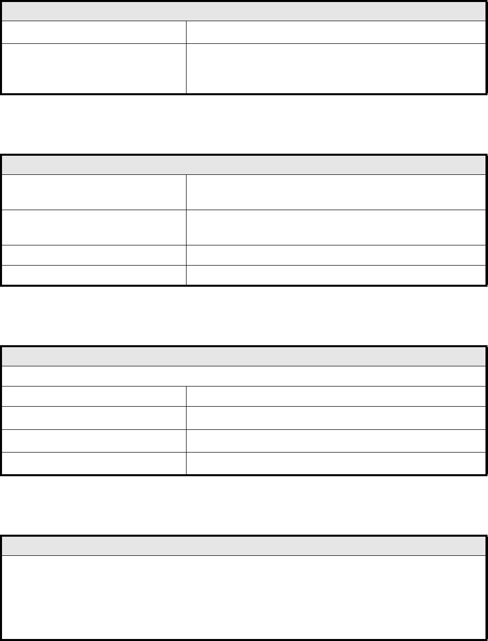
Permissible environmental influences
Room temperature
Between 15
o
C and 35
o
C
Air humidity
30 to 75 %
(on average not higher than 45%, so that under no circum-
stances will there be condensation in or on the machine)
Machine control
Computer machine controller
PC 486
RMOS operating system
Computer station control
Pentium PC
MS-Windows NT 4.0 operating system
Machine control Siemens S5 input/output control
Axis controller Siemens axis controller boards (digital)
Compressed air specification
Max. particle size by density, based on ISO/DIS 8573-1 (Class 1)
Particle size 0.1 µm
Particle density
0.1 mg/m
3
Max. oil content (Class 1)
Particle density 0.01 mg/m
3
Pressure dewpoint (Class 4)
Dewpoint +3
o
Noise emission values specified in accordance with DIN 45 649-1
Emission value at a workstation (L
pAc
) 71 dB (A)
DIN EN ISO 11204 (i)
Sound power level (L
WAc
) 85 dB (A)
E-DIN EN ISO 3744 (i)
001-0307