80S-2080F480F4-680F5 User’s Manual.pdf - 第201页
4 Single Functi ons SIPLACE 80S-20/F4/F4-6 User’s Manual 4.3 Single Functions, Gantry with 6x Revolver Head (for 80F4-6) Edition 07/ 97 from Software Version SR.403.xx 4 - 36 4.3.6 Nozzle Configuration 6x Revolver Head T…
SIPLACE 80S-20/F4/F4-6 User’s Manual 4 Single Functions
Edition 07/97 from Software Version SR.403.xx 4.3 Single Functions, Gantry with 6x Revolver Head (for 80F4-6)
4 - 35
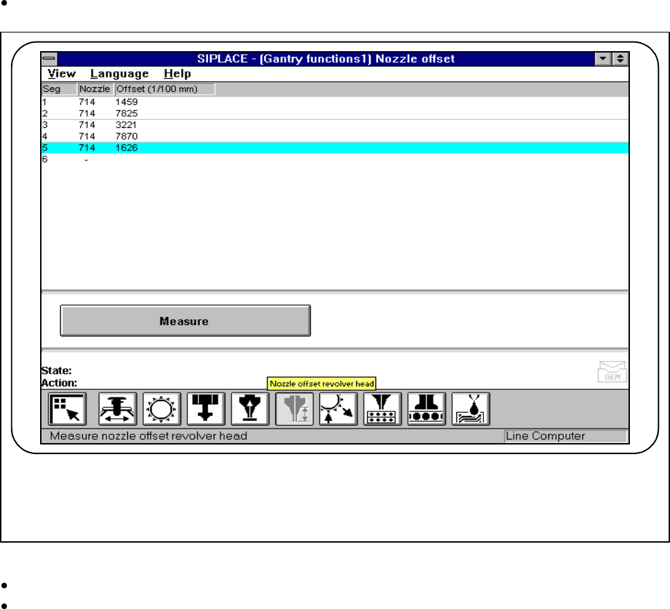
4.3.5 Nozzle Offset, 6x Revolver Head
This function is used for determining the nozzle height of all segments. If all segments are in the star the value
found here will refer to Segment 1.
In the In the Gantry functions menu click on the symbol button for Nozzle offset revolver head.
Fig. 4.3.7 Nozzle offset 6x revolver head
Click on the Measure button.
Press the Start button when you are asked to do so on the screen. The active gantry will move to a defined
position above the board conveyor and there carry out measurement of the z height with all segments.
Once measurement is finished the gantry will return to its starting position. The measured nozzle heights
will now be displayed.
F
4 Single Functions SIPLACE 80S-20/F4/F4-6 User’s Manual
4.3 Single Functions, Gantry with 6x Revolver Head (for 80F4-6) Edition 07/97 from Software Version SR.403.xx
4 - 36
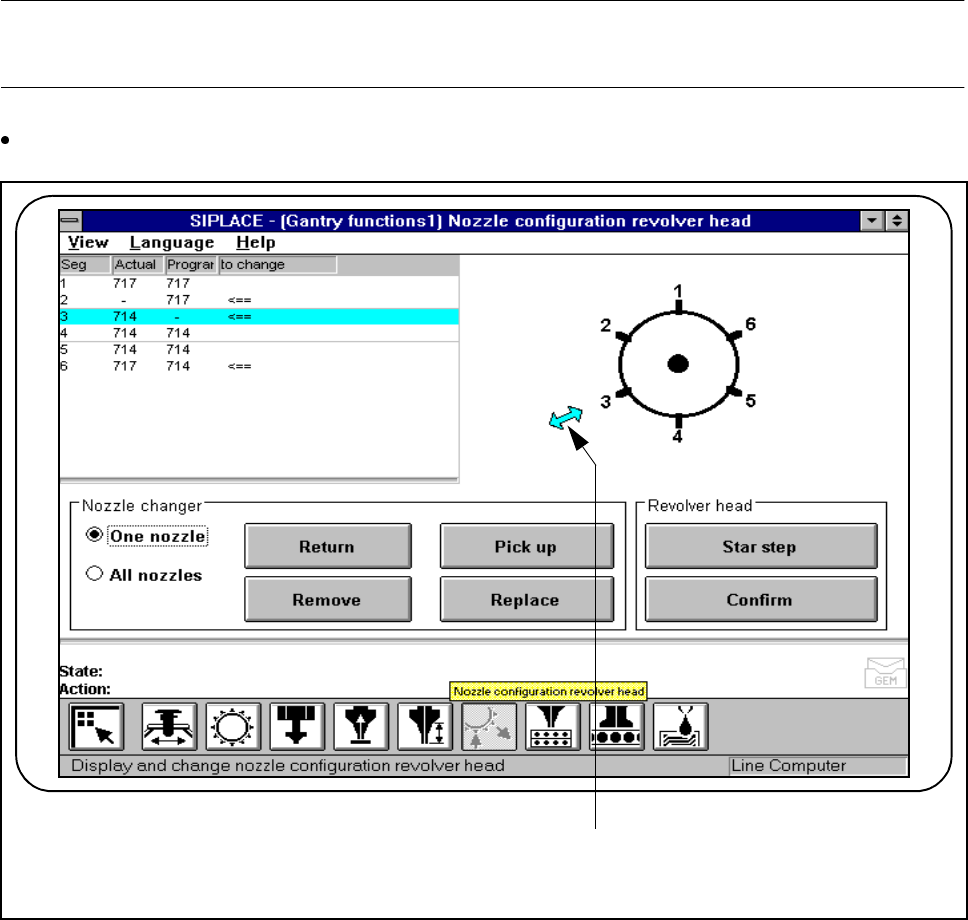
4.3.6 Nozzle Configuration 6x Revolver Head
This function is used for displaying, checking and changing the nozzle sizes of the nozzles at the placement
head.
NOTE
Editing or confirming the sizes is only possible with the specified clusters and set-up.
In the Gantry functions menu click on the symbol button for Nozzle configuration revolver head.
Fig. 4.3.8 6x revolver head nozzle configuration
- Key to Fig. 4.3.8
1 Changeover position
F
1

SIPLACE 80S-20/F4/F4-6 User’s Manual 4 Single Functions
Edition 07/97 from Software Version SR.403.xx 4.3 Single Functions, Gantry with 6x Revolver Head (for 80F4-6)
4 - 37
4.3.6.1 6x Revolver Head - Star Step
When this function is activated the revolver head is advanced each time by a step of one segment. The seg-
ment which is in the changing position is indicated by an arrow ( <== ) (see Fig. 4.3.8) on the revolver head
diagram.
Nozzles which have to be changed are marked in the To change column by an arrow ( <== ).
Within the Revolver head working area click on the Star step button. The revolver head is advanced by a
step and the changing position displayed.
4.3.6.2 Confirm
When this function is activated, changing a requested nozzle is confirmed.
This acknowledgment is required with different nozzle configurations ( programmed and actual) if the Pro-
grammed column’s contents is to be transferred into the Actual column (<== in the To change column).
This new nozzle configuration is saved to the aktuell.ma machine data file. In all cases the star position pro-
cessed will be the one which is shown in the changing position (<== in the revolver head diagram).
Before confirmation the nozzle at the segment must be changed accordingly.
Once processing has finished the two columns (Programmed and Actual) must be the same.
l Procedure
Cycle the nozzle on the revolver head which is to be changed
(<== in the Change nozzle ) to the changing position.
Change the nozzle in accordance with the programmed nozzle configuration.
Within the working area ’Revolver head’ click on the Confirm button.
Once processing has finished the two columns (Programmed and Actual) must be the same.
4.3.6.3 One nozzle - Return (with Nozzle Changer Only)
When this function is activated, a specific nozzle on the revolver head can be returned to the correct maga-
zine of the nozzle changer.
Click on the "One nozzle“ button in the "Nozzle changer“ work area.
Click on the Return button. An input box will appear on screen.
Enter the desired nozzle number in the input box and click on OK to confirm.
The selected nozzle will be returned to the correct magazine of the nozzle changer.