80S-2080F480F4-680F5 User’s Manual.pdf - 第379页
5 Vision Functions SIPLACE 80S-20/F4/F4-6/F5 User’s Manual 5.10 Test Component: Supplements to the 80F4, 80F4-6 or 80F5 Machines Ed ition 03/98 from Software Version SR.404.xx 5 - 158 Line engine er 5.10.1 Select Pa ckag…
SIPLACE 80S-20/F4/F4-6/F5 User’s Manual 5 Vision Functions
Edition 03/98 from Software Version SR.404.xx 5.10 Test Component: Supplements to the 80F4, 80F4-6 or 80F5 Machines
Line engineer 5 - 157
5.10
Test Component
: Supplements to the 80F
4
, 80F
4
-6
or 80F
5
Machines
On the 80F
4
, 80F
4
-6 or 80F
5
automatic placement machines, you can optically center fine-pitch components
with a maximum edge length of up to 55 mm with the IC camera. Components with an edge length exceeding
32 mm, multiple measurement is employed. In addition, you can also optically center BGAs using the IC sen-
sor.
Multiple measurement will be launched each time you access the Measure component or Test component
options.
The following conditions apply to multiple measurement:
1. The number of measurements to be carried out will be determined by the MVS system using a particular
algorithm. The component size and tolerance values will, for example, be input into this algorithm.
2. In the MVS system the combination of different measurement methods will be specified. You will not be
able to change the combination of methods nor the hex parameters.
With the FC camera you can optically center fine-pitch components and flip-chips.
As regards information on and definitions of BGAs, flip-chips and their measurement methods see Section
5.6.4.4, Page 5 - 88.
For information on the ball model description see Section 5.6.4.11 from Page 5 - 104.
In the Measuring mode menu (see Section 5.6.4.13, Page 5 - 106), you can select and activate different
measuring methods and modify the associated measuring parameter values.
Safety information on the component vision systems of the 80F
4
, 80F
4
-6 or 80F
5
machines
DANGER
You must not make any modifications whatsoever to or tamper with the safety features of the 80F
4
, 80F
4
-6 or
80F
5
machines or the IC or flip-chip modules.
The optical range of the IC and flip-chip camera conforms to laser class 1, provided that the camera is perma-
nently fixed in the automatic placement system and that the protective covers are closed (EN 60825-1 and
IEC 825).
Fig. 5.10.1 Identification label for Laser class 1
s
5 Vision Functions SIPLACE 80S-20/F4/F4-6/F5 User’s Manual
5.10 Test Component: Supplements to the 80F4, 80F4-6 or 80F5 Machines Edition 03/98 from Software Version SR.404.xx
5 - 158 Line engineer
5.10.1
Select Package Form
Menu
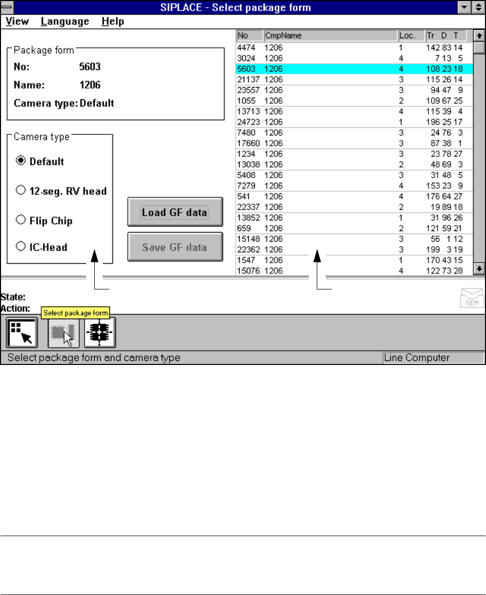
Following selection of the Test component menu the Select package form menu will drop down. Here you
can specify a package form and the corresponding camera type.
Fig. 5.10.2 Select package form menu
If you had previously changed measurement conditions or package form you will be asked where you wish to
discard or save the data. For a description of this please refer to Section 5.6.3 from Page 5 - 77.
The menu that appears after this query differs from that of the 80S-20 only in that the 80S-20 automatic place-
ment system has a component vision system on both revolver placement heads, while the 80F
4
/F
4
-6-auto-
matic placement system has a component vision system on the 12x or 6x revolver head, and one or two
component vision systems can be used on the machine frame for the IC placement head. The component
vision system with IC camera centers fine-pitch components and BGAs, while the component vision system
with FC camera centers flip-chips and fine-pitch components.
PLEASE NOTE
Only select the revolver head, IC head or IC head/flip-chip camera type if you want to insert components of
the same type with both the 12x or 6x revolver head and the IC head.
Camera type options field Lists field
SIPLACE 80S-20/F4/F4-6/F5 User’s Manual 5 Vision Functions
Edition 03/98 from Software Version SR.404.xx 5.10 Test Component: Supplements to the 80F4, 80F4-6 or 80F5 Machines
Line engineer 5 - 159
With the mouse pointer mark a component from the list field or the vision system in the Camera type
options field.
Click on the Load GF data button. The data are transferred to the program.
Click on the Main view symbol, break off the dialog without saving and return to the Main view menu.
5.10.2
Test Component
Menu
5.10.2.1
Select Component Type
Option
With the 80F
4
, 80F
4
-6 or 80F
5
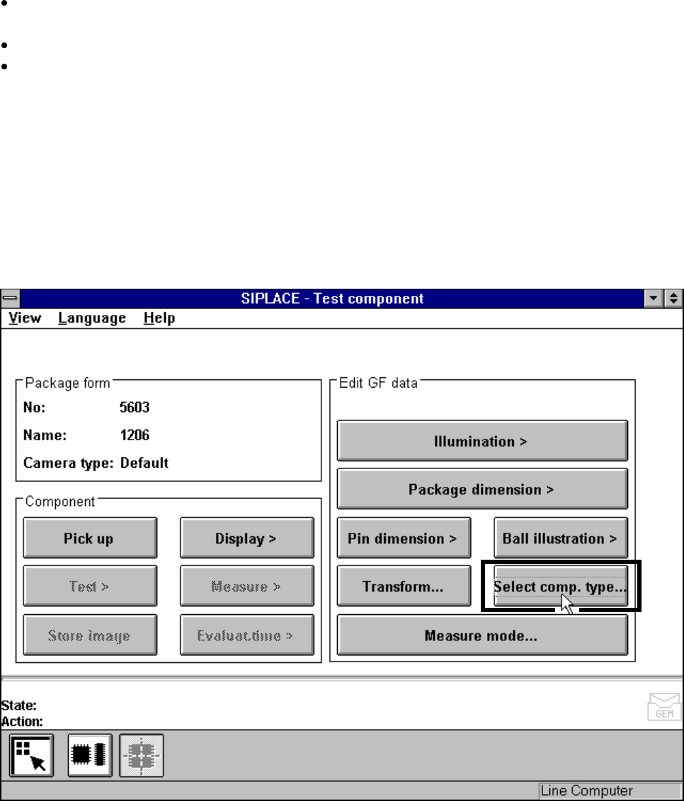
machines, the Test component menu (for a description see Section 5.10.2,
Page 5 - 159) also includes the Select component type option.
Fig. 5.10.3 Test component menu (80F
4
, 80F
4
-6 or 80F
5
)
When you select this option the following menu will open.