80S-2080F480F4-680F5 User’s Manual.pdf - 第66页
1 Operational Safety SIPLACE 80S-20/F4/F4-6/F5 User’s Manual 1.4 Disabling the compressed air supply and discharging the pressu re Edition 03/98 from SW SR.404.xx 1 - 24
SIPLACE 80S-20/F4/F4-6/F5 User’s Manual 1 Operational Safety
Edition 03/98 from SW SR.404.xx 1.4 Disabling the compressed air supply and discharging the pressure
1 - 23
1.4 Disabling the compressed air supply and dis-
charging the pressure
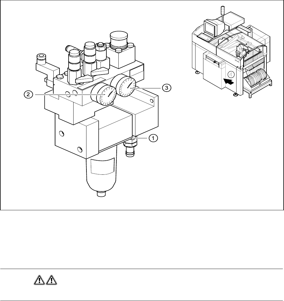
The compressed air working pressure is set to 5,1 bar, although it may fluctuate between 5.0 and 5.3 bar.
The position of the compressed air unit is indicated by item 4 in Fig. 1.4.1. The compressed air supply to the
automatic placement system can be interrupted using the shut-off valve (item 1 in Fig. 1.4.1).
- You must remove the cover plate to use the shut-off valve.
- Turn the lever on the shut-off valve (item 1 in Fig. 1.4.1) from the vertical to the horizontal position.
- Watch the working pressure gauge and the pressure gauge for the compressed air supply to the stopper
(item 2 and 3 in Fig. 1.4.1)
When the automatic placement system is switched on, the pressure discharges to 0 bar within 1 minute.
Fig. 1.4.1 Compressed air unit on the automatic placement system
- Key to Fig. 1.4.1
1 Shut-off valve lever in the ’CLOSED’ position 2 Working pressure gauge
3 Pressure gauge for the stopper working pressure 4 Position of the compressed air unit on the
placement system
WARNING
NEVER disconnect compressed air lines while they are pressurized. Risk of injury!
1 Operational Safety SIPLACE 80S-20/F4/F4-6/F5 User’s Manual
1.4 Disabling the compressed air supply and discharging the pressure Edition 03/98 from SW SR.404.xx
1 - 24
SIPLACE 80S-20/F4/F4-6/F5 User’s Manual 1 Operational Safety
Edition 03/98 from SW SR.404.xx 1.5 Energy state of automatic placement systems after switching off at the main switch
1 - 25
1.5 Energy state of automatic placement systems
after switching off at the main switch
DANGER
Automatic placement systems from the SIPLACE family are powered with 3 x 400 V ± 10 %, 50/60 Hz mains
voltage.
This means that parts of the system carry potentially fatal voltages - even when switched off at the main
switch.
Death, serious injury or considerable damage may result if these placement systems are handled incorrectly.
Always follow the applicable accident prevention and VDE regulations (particularly VDE 0113).
The guards over the control and servo units must ONLY be opened by appropriately qualified and trained per-
sonnel.
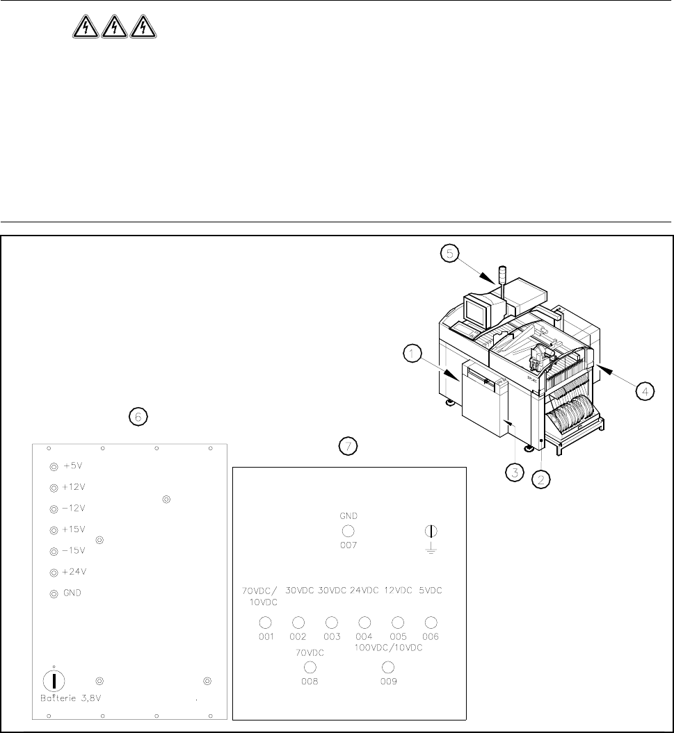
Fig. 1.5.1 Position of the control unit, servo unit, main switch, service socket and compressed air unit on placement systems
- Key to Fig. 1.5.1
1 Main switch Q1 2 Service socket
3 Compressed air unit 4 Servo unit
5 Control unit 6 Control unit measuring unit
7 Servo unit measuring unit
un-
switched
switched