80S-2080F480F4-680F5 User’s Manual.pdf - 第481页
9 Maintenance SIPLACE 80S-20/F4/F4-6/F5 User’s Manual 9.3 Machine Base Ed ition 03/98 from Software Version SR.404.xx 9 - 32 NOT E If, desp ite ch anging the filter car tridges, th e manom eters stil l do not s how 5.0 b…
SIPLACE 80S-20/F4/F4-6/F5 User’s Manual 9 Maintenance
Edition 03/98 from Software Version SR.404.xx 9.3 Machine Base
9 - 31
Using your finger, push the drain plug (see point 2 in Fig. 9.3.5, page 9 - 29) at the bottom end of the filter
hose (see point 3 in Fig. 9.3.5, page 9 - 29) up so that the condensate can drain into the tray.
Then open the shut-off valve for the compressed air supply (see point 12 in Fig. 9.3.5, page 9 - 29). The
drain plug will close automatically.
9.3.5.4 Replacing the Filter Cartridge, Cleaning the Filter Bowl
PLEASE NOTE
Make sure that there are no components on the placement heads when you carry out this work since the
automatic placement system must be switched off.
DANGER
• Switch off the automatic placement systems at the main switch and disconnect from the power supply.
• Switch off the compressed air supply at the shut-off valve in the compressed air unit.
Remove the cover plate from the compressed air unit (see Fig. 9.1.1, page 9 - 3).
In addition turn off the compressed air supply at the stop valve of the compressed air unit (see Fig. 9.3.5,
page 9 - 29).
Wait a few moments until the lines have depressurized.
WARNING
Never push the drain plug with a screwdriver in order to depressurize the lines.
Both manometers (see points 4 and 11 in Fig. 9.3.5, page 9 - 29) must read 0.
Remove the filter bowl by rotating it a quarter-turn and pulling it downwards (bayonet closure).
Clean the filter bowl if necessary. Never use acidic cleaning agents. Only use soapy water for this work.
Empty the condensate container.
Unscrew and remove the support spring and remove the sealing ring.
Pull the filter cartridge downwards and out.
Slide in the new filter cartridge.
Place the seal on the threaded rod and then screw on the support spring. The black plastic disk must be
placed in the filter bowl.
Screw the filter bowl back on.
Open the stop valve of the compressed air supply (see Fig. 9.3.5, page 9 - 29).
Switch the machine back on at the main switch.
Check the pressure at both manometers:
– operating pressure of the lefthand manometer: 5.6 bar
– operating pressure for the stopper at the right-hand manometer: stopper: 2.3 bar

9 Maintenance SIPLACE 80S-20/F4/F4-6/F5 User’s Manual
9.3 Machine Base Edition 03/98 from Software Version SR.404.xx
9 - 32
NOTE
If, despite changing the filter cartridges, the manometers still do not show 5.0 bar and 2.3 bar this will be
due to other reasons, as described in Section 9.3.5.1 on page 9 - 28.
Reinsert the cover plate.
SIPLACE 80S-20/F4/F4-6/F5 User’s Manual 9 Maintenance
Edition 03/98 from Software Version SR.404.xx 9.3 Machine Base
9 - 33
9.3.6 Emptying the Rejects Container for the IC Head (SIPLACE 80F
4
/
80F
4
-6/F
5
)
As regards the position of this rejects container at the machine base, please refer to Fig. 9.3.6.
The machine is switched off at the main switch and the sliding safety hoods are open.
Check first whether the z axis (sleeve) is in its top end position. If it is not, this indicates a fault. You should
inform Siemens’ SMD service department.
Move the gantry away from the rejects container by hand. Only hold the gantry and never the placement
head.
Lift the rejects container vertically upwards and off the magnetic disk, making sure that no components
drop into the working area of the machine.
Place the empty container back in the center of the magnetic plate.
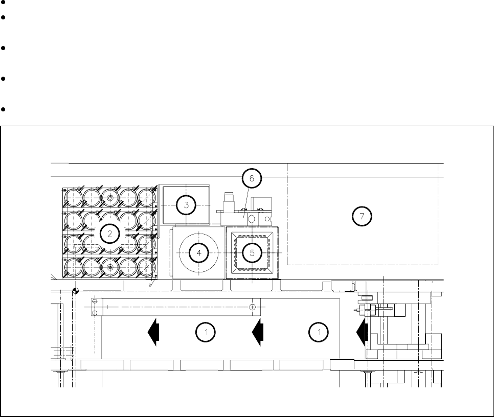
Fig. 9.3.6 Emptying the rejects container for the IC head, position at the machine base
- Key to Fig. 9.3.6
1 Direction of PCB transport
2 IC head nozzle changer
3 Rejects container for IC head
4 Flip-chip sensor
5 IC sensor
6 Coplanarity module
7 Wafflepack changer