80S-2080F480F4-680F5 User’s Manual.pdf - 第574页
SIPLACE 80 S20/F4/F4-6/F5 User’s Manual 10 Component Handling Edition 03/98 from S oftware Version SR.404.xx 10.6 Wafflepack Changer 10 - 21 10.6.3 Principle of the Wafflepack Changer With the wa fflepack changer on the …

10 Component Handling SIPLACE 80 S20/F4/F4-6/F5 User’s Manual
10.6 Wafflepack Changer Edition 03/98 from Software Version SR.404.xx
10 - 20
10.6.2 General Information
The use of flatpack ICs is gaining more and more importance in the manufacture of printed circuit boards.
These components have now reached the point where they are almost always delivered on trays (wafflepack
magazines).
The space taken up by magazine trays is however relatively high when compared with the component den-
sity. In addition, due to their low holding capacity, the wafflepack magazines must frequently be changed and
if this has to be done by hand this necessarily involves interrupting the placement process.
But when a wafflepack changer is used there is no time lost unnecessarily in the storing and automatic chang-
ing of the wafflepack magazines. Programmed access to up to 28 freely selectable wafflepack magazines
also increases the range of available components.
NOTE
The wafflepack changer is located on the lefthand side of the SIPLACE 80 F table.
The wafflepack changer does not require the entire width of the component table. On this side of the table
10 locations remain free which can be used for the 20 x 8 mm tape module, for example.
SIPLACE 80 S20/F4/F4-6/F5 User’s Manual 10 Component Handling
Edition 03/98 from Software Version SR.404.xx 10.6 Wafflepack Changer
10 - 21
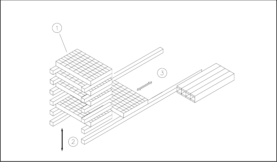
10.6.3 Principle of the Wafflepack Changer
With the wafflepack changer on the SIPLACE 80 F it is possible to hold up to 28 wafflepack magazines and to
change these fully automatically. The trays (level) for the wafflepack magazines are numbered in sequence
from bottom to top, with the lowest number at the bottom (1 - 28).
The magazine storage unit travels vertically until the level selected lies with in the travel range of the horizon-
tal axis. The horizontal axis then removes the tray from the level and transfers it into the access area of the
placement head.
The following Fig. 10.6.2 shows the basic principle behind the wafflepack changer.
Fig. 10.6.2 Principle of the wafflepack changer
- Key to Fig. 10.6.2
1 Magazine storage unit 2 Lift
3 Horizontal axis
10.6.3.1 Functional Sequence
l Requirements
Flatpack magazines with the corresponding components are defined in the set-up.
After set-up conversion the magazine storage unit will make a reference run.
The PCB camera approaches the fiducials which are marked on a strip (see Fig. 10.6.3).
10 Component Handling SIPLACE 80 S20/F4/F4-6/F5 User’s Manual
10.6 Wafflepack Changer Edition 03/98 from Software Version SR.404.xx
10 - 22
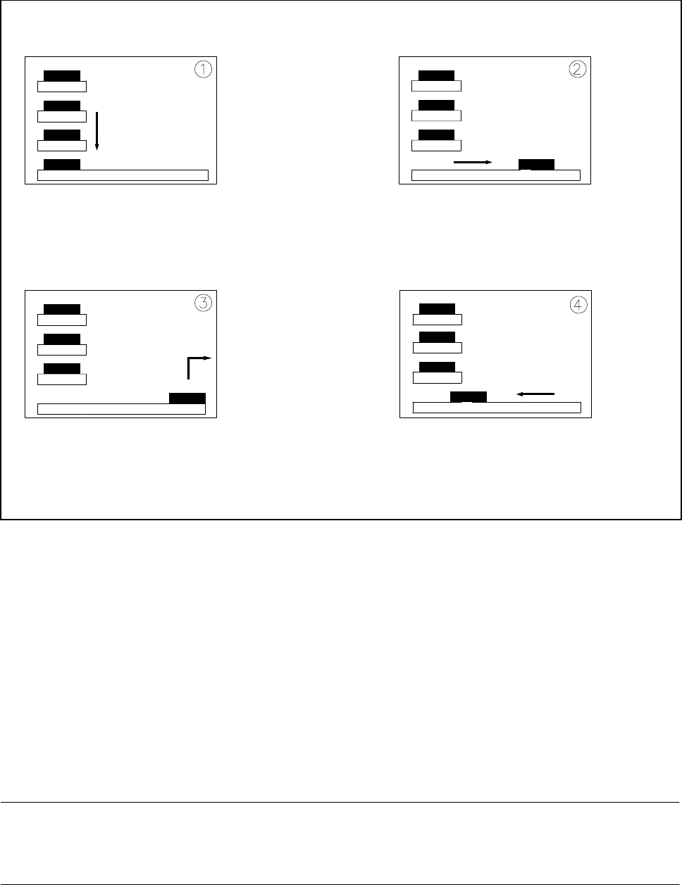
Fig. 10.6.3 Functional sequence
- Key to Fig. 10.6.3
1 The selected level of the magazine storage unit is positioned on the feeder axis (horizontal).
2 The tray is transferred to the access area of the placement head.
3 The components are removed.
4 The tray is returned again.
- The lift in the magazine storage unit brings the tray from the selected level into position on the horizontal
feeder axis.
- The tray with the flatpack magazine is brought into the placement head’s access area.
- Once the desired components have been removed by the placement head, the magazine is returned in the
reverse sequence of operations.
NOTE
If the placement sequence is interrupted with the wafflepack changer being switched off, the set-up and the
current fill level will remain saved in memory.
- If the placement sequence is restarted using the set-up which was being used when the sequence was
aborted, the placement machine will be able to pick up the next component from the point where it picked
up the previous one.
- The position of the trays in the flatpack magazine storage unit and the components they are filled with is