80S-2080F480F4-680F5 User’s Manual.pdf - 第601页
11 Station Extensions/Options SIPLACE 80S-20/F4/F4-6/F5 User’s M anual 11.1 Nozzle Changer for the 12x R evolver Head Edition 03/98 f rom Software Version SR.404.xx 11 - 4 11.1.2 Technical Data 11.1.3 Method of Function …
SIPLACE 80S-20/F4/F4-6/F5 User’s Manual 11 Station Extensions/Options
Edition 03/98 from Software Version SR.404.xx 11.1 Nozzle Changer for the 12x Revolver Head
11 - 3
11.1 Nozzle Changer for the 12x Revolver Head
11.1.1 Overview
The nozzle-changer is used with the SIPLACE 80S-20/80F
4
machines. One nozzle-changer is required per
revolver head. It is modular in design and consists of a minimum of 1 and a maximum of 7 trays.
Each of these trays accommodates 12 nozzle garages (see Fig. 11.1.2). The trays are placed on a shared
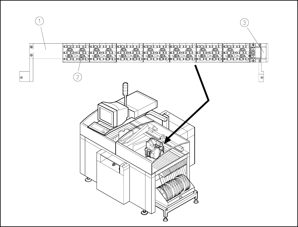
support located in the space between the board conveyor and the feeder modules (see Fig. 11.1.1). The posi-
tions of the trays relative to one another is determined by two parallel pins.
Fig. 11.1.1 Location of the nozzle changer in the SIPLACE 80S-20
- Key to Fig. 11.1.1
1 Carrier 2 Tray
3 Reject position

11 Station Extensions/Options SIPLACE 80S-20/F4/F4-6/F5 User’s Manual
11.1 Nozzle Changer for the 12x Revolver Head Edition 03/98 from Software Version SR.404.xx
11 - 4
11.1.2 Technical Data
11.1.3 Method of Functioning
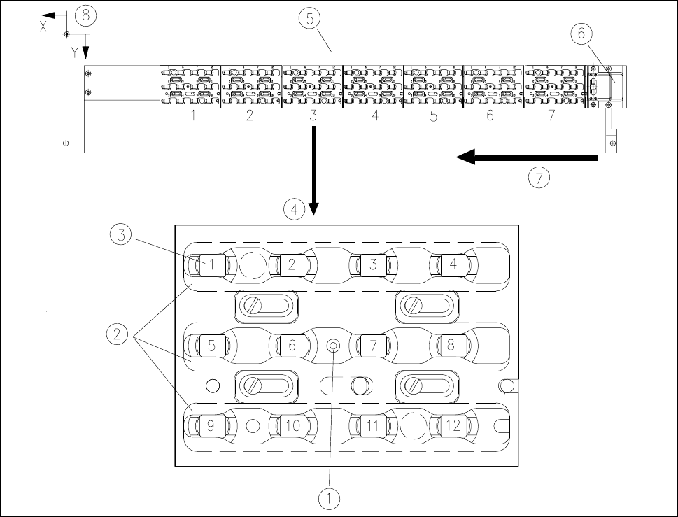
Each individual tray of the nozzle-changer holds a position fiducial for position recognition.
The individual locations of the trays are marked with the numbers 1 to 7 on the nozzle-changer. The individual
nozzle garages are continuously numbered from 1 to 12 in the trays (see Fig. 11.1.2).
NOTE
After consultation with Siemens PL EA 1 E special trays can be prepared and will be given a special coding.
The fixing of the position of the nozzles in the garages takes place via a key plate which can be moved along
an axis by 6 mm. The nozzles will be clamped or released depending on the position of the plate.
The plate is moved by means of a pneumatic cylinder simultaneously for all trays or all nozzles. All nozzles
are held or released simultaneously.
If no nozzle change has been carried out, the key plate will always be in the closed position.
l Picking up a nozzle
- The z axis of the revolver head moves downwards.
- The key plate opens.
- The z axis moves up.
Nozzle changer for revolver head
Installation space (length x width x height) 560 mm x 60 mm x 46 mm
Number of nozzle garages min.12 / max.84
Nozzle types which can be set up 7xx
Cover opening and closing < 200 ms
Capacity of reject container approx. 50 nozzles
Pneumatic system Pneumatic supply line, 5.5 bar
SIPLACE 80S-20/F4/F4-6/F5 User’s Manual 11 Station Extensions/Options
Edition 03/98 from Software Version SR.404.xx 11.1 Nozzle Changer for the 12x Revolver Head
11 - 5
l Returning a nozzle
- The key plate opens.
- The z axis moves downwards.
- The key plate closes.
- The z axis moves up.
Fig. 11.1.2 Overview of trays and nozzle garages
- Key to Fig. 11.1.2
1 Position fiducial 2 Key plate
3 Nozzle garage 4 Tray
5 Nozzle changer 6 Reject position
7 Direction of transport
l Rejecting defective nozzles
- At the reject position the z axis travels a 14 mm stroke.
- The z axis moves upward and the nozzle is pulled off the sleeve by a spring wire.