80S-2080F480F4-680F5 User’s Manual.pdf - 第534页
SIPLACE 80S-20/F4/F4-6/F5 User’s Manual 9 Maintenance Edition 03/98 from S oftware Version SR.404.xx 9.7 6x Revolver Head (80 00) 9 - 85 9.7.5 Greasing the Z Drive Unit Materials and Equipment A clean and li nt-free cl o…
9 Maintenance SIPLACE 80S-20/F4/F4-6/F5 User’s Manual
9.7 6x Revolver Head (8000) Edition 03/98 from Software Version SR.404.xx
9 - 84
With one hand prevent the sleeve from rotating. You can do this by holding it at the drive surface with your
fingers (B).
Push the new nozzle onto the sleeve as far as the stop (C).
If the nozzle cannot be turned further against the sleeve, then the latching pin (see point 4) is already
engaged in the latching groove (3) of the nozzle.
If the nozzle is not yet engaged, turn it clockwise until you can feel that it has latched in place.
PLEASE NOTE
Do not use too much force when you turn the nozzle against the sleeve since this could cause the color
coding on the nozzle to be damaged by the latching pin (4).
9.7.4 Replacing the Silencer
Spare Part
Silencer, from item no. 00320964-01
Remove the silencer by hand by rotating it clockwise.
Pull out the threaded rod and remove the funnel from the silencer.
Replace the silencer.
To fit the new silencer proceed in the reverse sequence of operations.
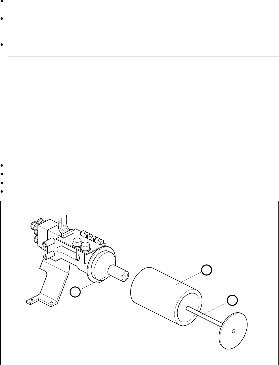
Fig. 9.7.6 Replacing the silencer
- Key to Fig. 9.7.6
1 Threaded rod
2Silencer
3 Funnel
3
1
2
SIPLACE 80S-20/F4/F4-6/F5 User’s Manual 9 Maintenance
Edition 03/98 from Software Version SR.404.xx 9.7 6x Revolver Head (8000)
9 - 85
9.7.5 Greasing the Z Drive Unit
Materials and Equipment
A clean and lint-free cloth
Staburags N12 lubricating grease, from item no. 02100611-01
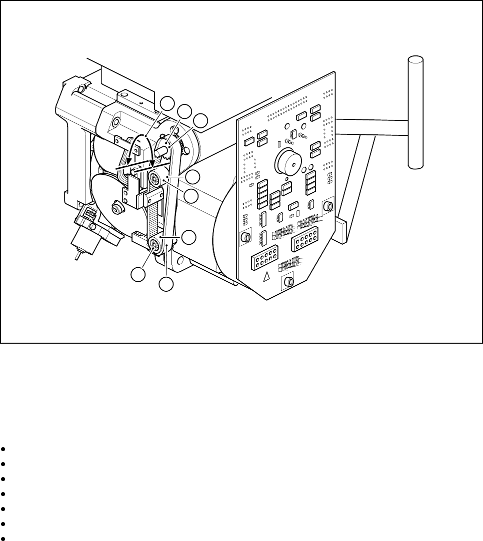
Fig. 9.7.7 Greasing the z drive unit
- Key to Fig. 9.7.7
1 Synchroflex toothed belt
2 Synchronizing pulley
3 Deflection wheels
Move the z axis to its top limit position.
Apply a little Staburags to a clean and lint-free cloth.
Grease the toothed belt sparingly in the area indicated in Fig. 9.7.7 (A).
Apply grease sparingly to the synchronizing pulley (B).
Apply grease sparingly to both deflection wheels.
Move the z axis back and forth repeatedly.
Wipe off excess grease with a cloth.
1
2
B
3
3
A
C
C
9 Maintenance SIPLACE 80S-20/F4/F4-6/F5 User’s Manual
9.7 6x Revolver Head (8000) Edition 03/98 from Software Version SR.404.xx
9 - 86
9.7.6 Cleaning Vacuum/Forced Air Valves
9.7.6.1 Removing the Valve Plunger
Position the gantry concerned, with the revolver placement head over the PCB conveyor.
Switch off the placement system and disconnect the power supply.
Disconnect the compressed air supply.
Starting from the middle remove several feeders from the components changeover table.
Carefully push the gantry out to the stop by hand.
Depending on the valve adjustment drive responsible for prompting the error message you have to turn the
star by a certain angle to be able to remove and to clean the faulty valve:
Fault prompted by the ’pick-up/place’ valve adjustment drive
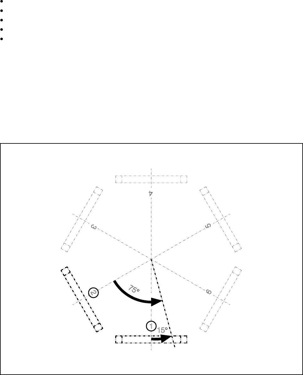
This valve adjustment drive is situated in star station 1 (see pos. 1, Fig. 9.7.8). Using your fingers, carefully
turn the star 15° counter-clockwise. 15° corresponds to a quarter turn of the star.
Fault prompted by the ’reject’ valve adjustment drive
This valve adjustment drive is situated in star station 3 (see pos. 3, Fig. 9.7.8). Using your fingers, carefully
turn the star 75° counter-clockwise. 75° corresponds to one and a half turns of the star.
Fig. 9.7.8 Positioning the star for valve plunger removal
- Key to Fig. 9.7.8
1 Position of the ’pick-up/place’ valve adjustment drive 3 Position of the ’reject’ valve adjustment drive