80S-2080F480F4-680F5 User’s Manual.pdf - 第122页
SIPLACE 80S-20/F4/F4-6/F5 User’s Manual 2 Introduction and Basic Concepts Edition 03/98 from Software V ersion SR.404.xx 2.4 Brief D escription and Principles of the User Interface 2 - 45 2.4.4.10 Flux Application (Optio…
2 Introduction and Basic Concepts SIPLACE 80S-20/F4/F4-6/F5 User’s Manual
2.4 Brief Description and Principles of the User Interface Edition 03/98 from Software Version SR.404.xx
2 - 44
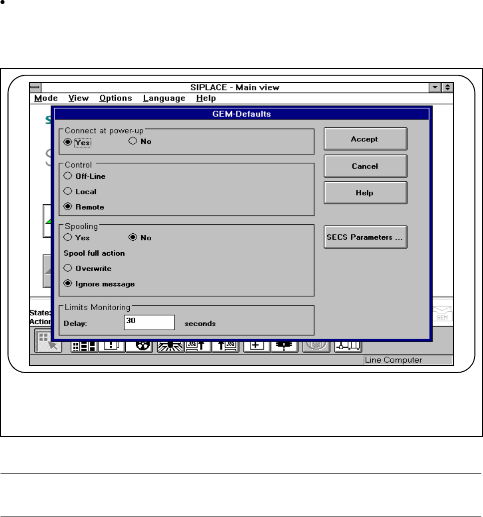
2.4.4.9 GEM Default Settings (Option)
Click on the GEM default settings option in the Options menu to set the default settings for the GEM
option on the station computer.
In this menu, you can set various parameters for the GEM interface. These will be used as standard
parameters for the SIPLACE station when it is switched on.
Fig. 2.4.12 Example of a GEM default setting
PLEASE NOTE
The complete range of functions is described in Section 11.9 of this User’s Manual.
SIPLACE 80S-20/F4/F4-6/F5 User’s Manual 2 Introduction and Basic Concepts
Edition 03/98 from Software Version SR.404.xx 2.4 Brief Description and Principles of the User Interface
2 - 45
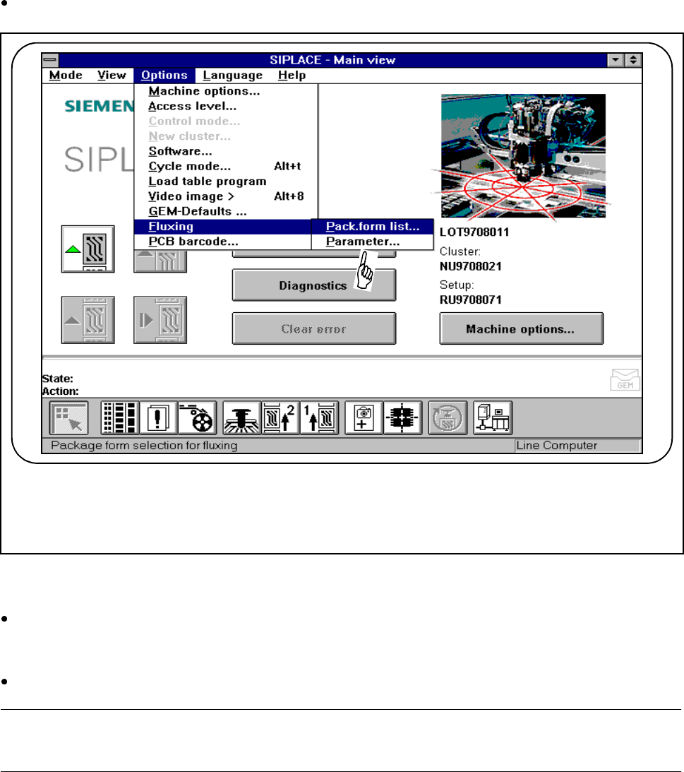
2.4.4.10 Flux Application (Option)
In order to apply flux for placing flip-chips on a PCB, the process data for the flip-chip must be entered in a list
and general flux application parameters must be entered on the station computer.
Select the Fluxing submenu from the Options menu on the menu bar
.
Fig. 2.4.13 Flux application option
l Package form list
Use this menu to add and edit flip-chip components with an associated package form (GF) no.
l Parameters
Select the "Parameters“ menu in order to specify data for the flux application sequence.
PLEASE NOTE
The complete range of functions is described in Chapter 11 of this User’s Manual.
2 Introduction and Basic Concepts SIPLACE 80S-20/F4/F4-6/F5 User’s Manual
2.4 Brief Description and Principles of the User Interface Edition 03/98 from Software Version SR.404.xx
2 - 46
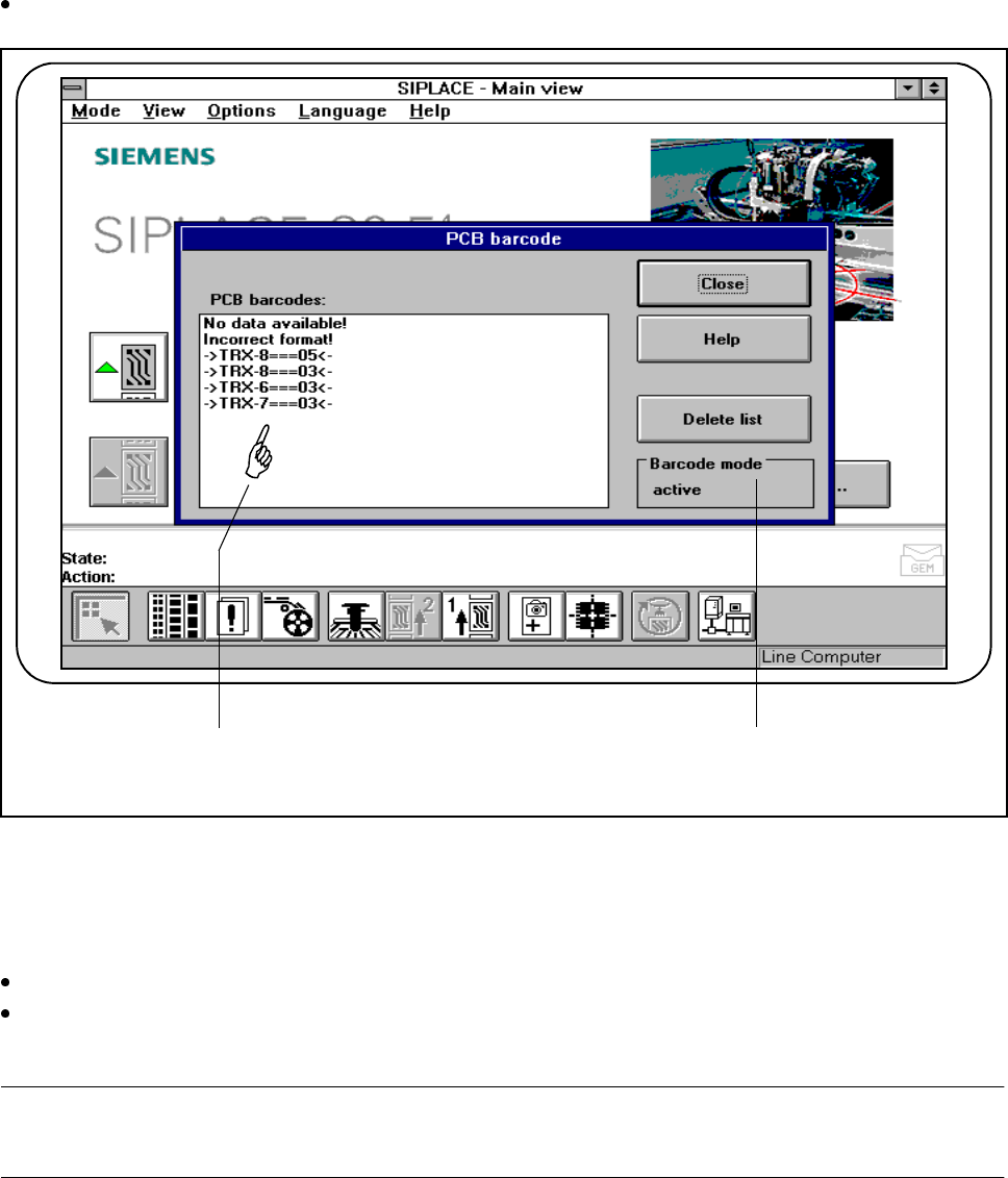
2.4.4.11 Display PCB Barcode (Option)
This menu is used to display the last barcode to be read by the PCB barcode reader in a list box.
It also indicates whether the barcode was read incorrectly or a start signal or the wrong signal occurred, or
whether no data was available.
Select the PCB barcode submenu from the Options menu on the menu bar.
Fig. 2.4.14 Display PCB barcode
- Key to Fig. 2.4.14
1 List box 2 Status display
Click on the Delete list button to delete the list.
The status display in the menu window shows the operating status for barcode mode. This operating sta-
tus is activated and deactivated by the line computer.
PLEASE NOTE
This menu is only active if the PCB bar code option has been installed and activated in the machine options.
1 2