80S-2080F480F4-680F5 User’s Manual.pdf - 第237页
5 Vision Functions SIPLACE 80S-20/F4/F4-6/F5 User’s Manual 5.1 Overview of the Vision Systems in the SIPLACE 80S-20 /F4/F4-6/F5 Machines Edition 03/98 from Software Version SR.404.xx 5 - 16 Line engine er Fig. 5.1.13 Vis…
SIPLACE 80S-20/F4/F4-6/F5 User’s Manual 5 Vision Functions
Edition 03/98 from Software Version SR.404.xx 5.1 Overview of the Vision Systems in the SIPLACE 80S-20/F4/F4-6/F5 Machines
Line engineer 5 - 15
The PCB position recognition camera system is located on the underside of the gantry. As a standard it cen-
ters board sizes from a minimum of 50 mm x 50 mm to a maximum of 460 mm x 460 mm, but with an optional
maximum of 508 mm x 460 mm. Board thickness may range between 0.5 mm and 3 mm.
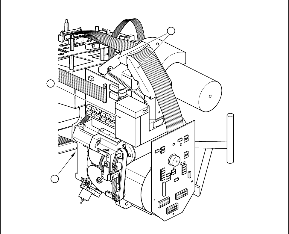
Fig. 5.1.12 Camera systems for PCB and component position recognition at the 6x revolver head
(with standard component vision system) of the 80F
5
placement machines
- Key to Fig. 5.1.12
1 Deflection mirror and component lens 2 Component camera
3 PCB camera on the underside of the gantry
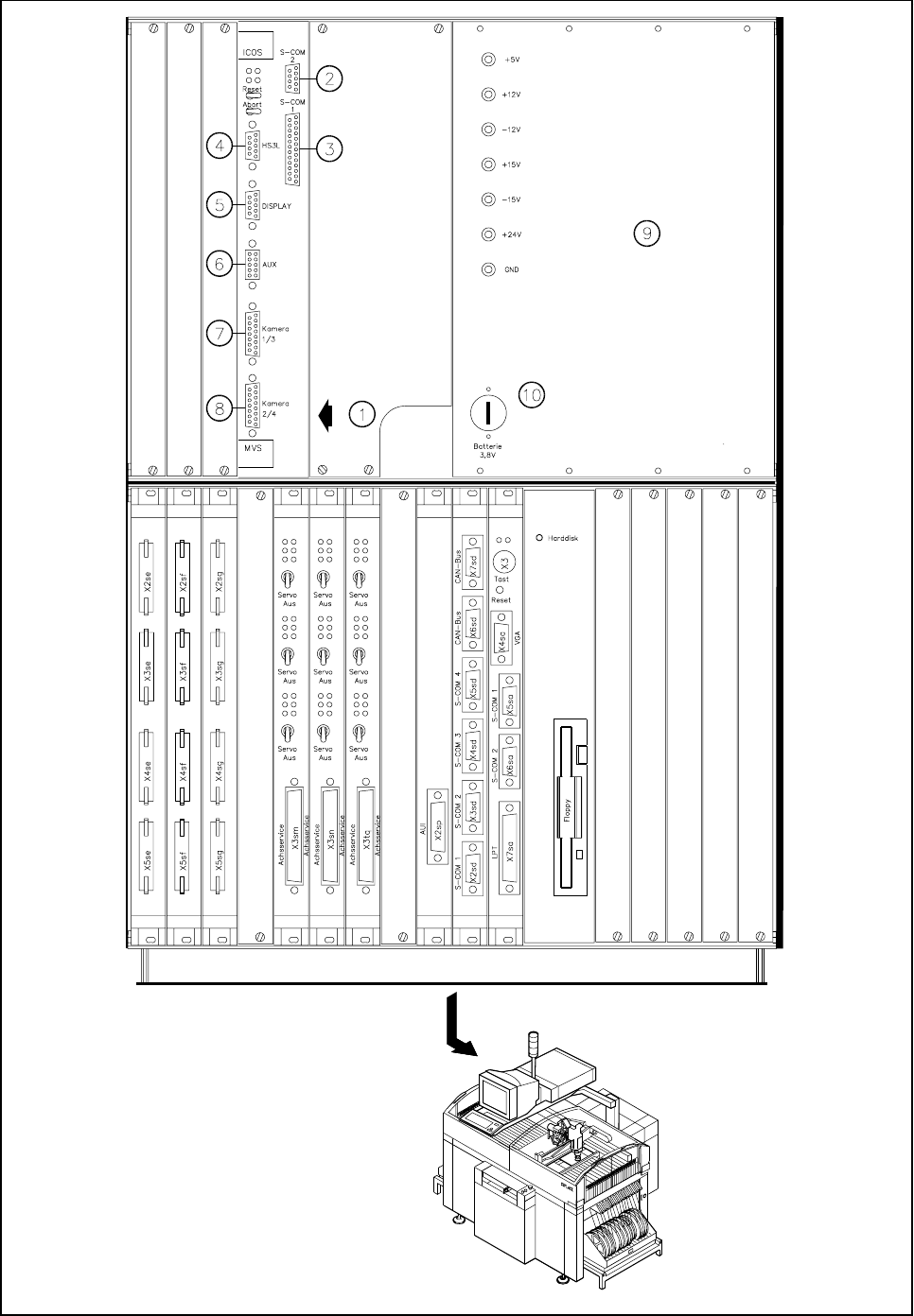
The evaluation unit (ICOS MVS system) which is accommodated in the machine’s control unit (see Fig.
5.1.13, Page 5 - 16) processes and evaluates the signals from the PCB and component camera systems of
the 6x revolver and IC placement heads. The deviations from the nominal values are used for determining
correction values which are then used in the recalculation of the placement positions and the skew of the
components to be inserted.
- Key to Fig. 5.1.13
1 PCB and component evaluation unit of vision system 2 COM2
3 COM1 4 HS3L communication port
5 Screen connection (SVGA) 6 Trigger flash connection
7 Camera connections 8 Camera connections
1 PCB camera 2 IC-head camera
3 Component camera, 6x revolver head 4 FC camera, IC-head
9 Power supply unit 10 Battery
3
1
2
5 Vision Functions SIPLACE 80S-20/F4/F4-6/F5 User’s Manual
5.1 Overview of the Vision Systems in the SIPLACE 80S-20/F4/F4-6/F5 Machines Edition 03/98 from Software Version SR.404.xx
5 - 16 Line engineer
Fig. 5.1.13 Vision evaluation unit in the SIPLACE 80F
5
placement machine
SIPLACE 80S-20/F4/F4-6/F5 User’s Manual 5 Vision Functions
Edition 03/98 from Software Version SR.404.xx 5.1 Overview of the Vision Systems in the SIPLACE 80S-20/F4/F4-6/F5 Machines
Line engineer 5 - 17
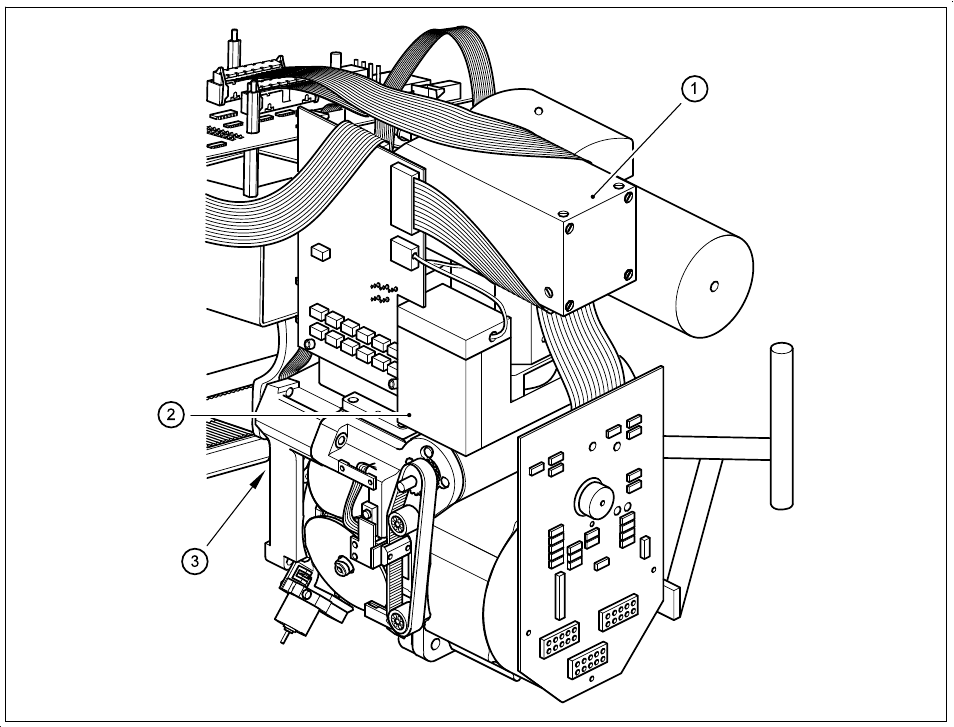
Fig. 5.1.14 Camera systems for PCB and component position recognition at the 6x revolver head
(with with component vision system for flip-chips, bare dies and standard components) of the 80F
5
machines
- Key to Fig. 5.1.14
1 Deflection mirror and component lens 2 Component camera
3 PCB camera on the underside of the gantry
The evaluation unit (ICOS MVS system) which is accommodated in the machine’s control unit (see Fig.
5.1.13, Page 5 - 16) processes and evaluates the signals from the PCB and component camera systems of
the 6x revolver and IC placement heads. The deviations from the nominal values are used for determining
correction values which are then used in the recalculation of the placement positions and the skew of the
components to be inserted.