80S-2080F480F4-680F5 User’s Manual.pdf - 第405页
6 What should you do ... ? SIPLACE 80S-20/F4/F4-6/F5 User’s Manual 6.7 When you change the set-up Edition 03/98 from Software Vers ion SR.404.xx 6 - 14 Fig. 6.7.1 Cleaning the contact surface of the sliding rail for the …
SIPLACE 80S-20/F4/F4-6/F5 User’s Manual 6 What should you do ... ?
Edition 03/98 from Software Version SR.404.xx 6.7 When you change the set-up
6 - 13
6.7 When you change the set-up
Before changing the set-up, print out the set-up with a description of the job on the printer of the line com-
puter, as described in the ’UNIX line computer’ User’s Manual.
6.7.1 What you should note when changing the feeder module
Handle the feeder modules carefully when you insert them into or remove them from the component table.
Do not allow the supporting surfaces of the feeder modules to bang against the edges of the component
table.
Clean the supporting surfaces of the feeder modules.
– Remove any loose components.
– Remove any residues of the rubber lining or dirt from the contact surface of the feeder modules.
Clean the component tables.
– Use a vacuum cleaner or a short-bristled brush to do this.
RISK OF INJURY
Avoid removing components from the magnetic rail of the component table with your fingers because you may
hurt yourself with tiny splinters of metal. Use a brush instead.
6.7.2 What you should note when changing the component table
Set up the feeder modules in the external set-up area as shown in the set-up drawing. Follow the prelimi-
nary set-up instructions in section 6.6.
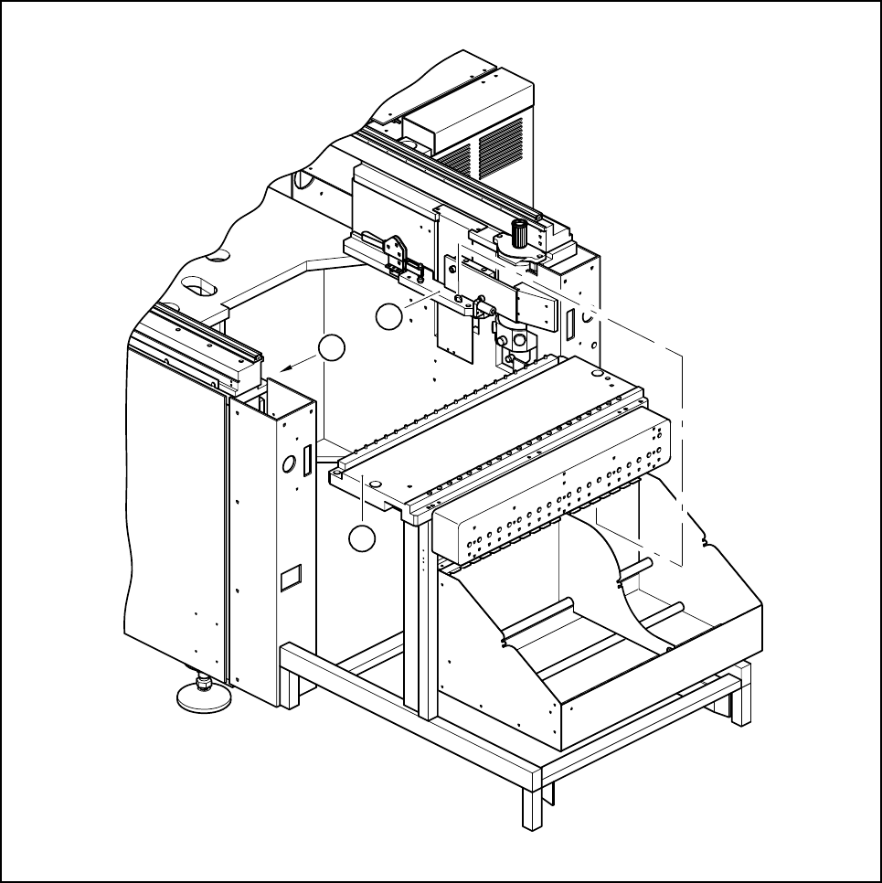
Make sure that contact surface of the sliding rail on the automatic placement machine (see Fig. 6.7.1) is
clean when you insert the component table.
PLEASE NOTE:
Insert the component table into the automatic placement machine carefully. Do not use too much force. If
the component table collides with the nozzle changer, it may be displaced and have to be recalibrated.
6 What should you do ... ? SIPLACE 80S-20/F4/F4-6/F5 User’s Manual
6.7 When you change the set-up Edition 03/98 from Software Version SR.404.xx
6 - 14
Fig. 6.7.1 Cleaning the contact surface of the sliding rail for the component table
Key to Fig. 6.7.1
1 Component table
2 Contact surfaces of the sliding rails for the component table
2
1
2

SIPLACE 80S-20/F4/F4-6/F5 User’s Manual 6 What should you do ... ?
Edition 03/98 from Software Version SR.404.xx 6.8 How to avoid track errors
6 - 15
6.8 How to avoid track errors
Make sure that the areas around the feeder modules are clean and that there are no loose components in
the vicinity of or under the feeder modules.
Ensure that the supporting surfaces of the feeder modules and particularly the magnetic rail of the compo-
nent tables are clean and level.
Refill with components in good time.
Splice the tapes in good time. This generally means that you prepare the splicing equipment when there is
still approximately 1.5 m tape on the reel.
Handle the feeder modules carefully when you insert them into or remove them from the component table.
These are high-precision devices.
When you insert the feeder modules, ensure that you do not accidentally press the program keys. If you
do, you could change the advance from 4 mm to 2 mm on 8 mm S feeder modules, for example.
Close the flaps of the feeder modules because they can be easily damaged when open.
With 8 mm S feeder modules, ensure that the components are picked up > 3mm from the front notch of
the pick-up position and < 3 mm from the rear notch of the pick-up position.
Check that all the plugs of the feeder modules are plugged in at the correct places.
6.8.1 ... on the 2 x 8 mm tape feeder module
Check the modules for external damage:
– Is the flap damaged?
– Has the foil removal beak become deformed?
– Is the tape pressure spring deformed or stretched?
Replace the old error message in the modules with the appropriate new message.
Pre-tension the foil removal device.
Check the foil removal force.
– The removal force is increased when the foil is pulled in.
– If the foil tears, then the removal force will become weaker.
Clean or adjust the cover foil winders if they are not running easily.
Replace the cover foil winders with empty winders in good time and have more empty winders ready at the
machine.
Check that you have placed the tape removal foil over the small deflection pulley.
Check that the tape removal foil is not twisted.
6.8.2 ... on the 8mm S tape feeder module
NEVER open the cover flap without first releasing the tension of the cover foil remover.
Set the pick-up position and the spacing of the tape with reference to the concise instructions enclosed
with each tape feeder module.
Introduce the tape material over the spring into the tape feeder module.