80S-2080F480F4-680F5 User’s Manual.pdf - 第242页
SIPLACE 80S-20/F4/F4-6/F5 User’s Manual 5 Vision Functi ons Edition 03/98 from S oftware Version S R.404.xx 5.2 PCB Vision System Line engi neer 5 - 21 fiduci al co ordinates – 1-D pattern s earch ( 1-dime nsional proces…

5 Vision Functions SIPLACE 80S-20/F4/F4-6/F5 User’s Manual
5.2 PCB Vision System Edition 03/98 from Software Version SR.404.xx
5 - 20 Line engineer
On the front side of the board are the connection sockets for
– the screen
– up to 4 camera inputs
– two serial interfaces (RS232 or RS422)
and the indicator LEDs for
– the CPU
– the vision processor
– the camera input
– the screen display.
The RESET and CANCEL switches are located beneath the indicator LEDs.
l the MVS camera interface (piggyback board) for up to four CCD cameras.
5.2.2 Technical Data
Camera model: SONY XC75
Number of pixels: Camera 768 (H) x 494 (V), Image 640 (H) x 484 (V)
Field of view: 5.7 mm x 5.7 mm
Illumination method: Incident light method (activated during measurement)
Image processing: Correlation principle, gray scale system
Processor cycle time: < 200 msec
Screen: RGB monitor (VGA mode) 640 x 484 pixels in the station computer
Fiducials: Library memory for up to 255 fiducial definitions
5.2.3 Description of Functions
Before placement the location, skew and shear of the board is determined by the PCB vision system using the
position of the fiducials. Deviations from the setpoint values are then included in the calculation of the place-
ment positions of the components as corrections.
A board must have at least 2 fiducials if the system is to be able to detect deviations in the board position and
the skew of the board. The presence of 3 fiducials will furnish additional information concerning compression
or stretching of the board or of the board layout.
5.2.4 Sequence of Functions
Before a fiducial can be used for board recognition it must first be ’taught’ to the machine. In other words, the
fiducial structure parameters must have been saved in the PCB vision system for that pattern.
The fiducial structure can be taught using the PCB vision camera mounted on the gantry and the vision
program. The vision evaluation unit determines the significant fiducial structure parameters using digital
image processing methods.
Measurement takes place in two stages:
– 2-D pattern search (2-dimensional process) in the coarse grid and provisional determination of the
SIPLACE 80S-20/F4/F4-6/F5 User’s Manual 5 Vision Functions
Edition 03/98 from Software Version SR.404.xx 5.2 PCB Vision System
Line engineer 5 - 21
fiducial coordinates
– 1-D pattern search (1-dimensional process) for a precise determination of the position of the fiducials.
With the 2-D pattern search process the template window is divided into moxel areas. Moxels (mosaic pixels)
are pixel fields containing for example 16 x 16, 8 x 8 pixels and so on. The lower the pixel count the higher the
resolution and the lower the search speed.
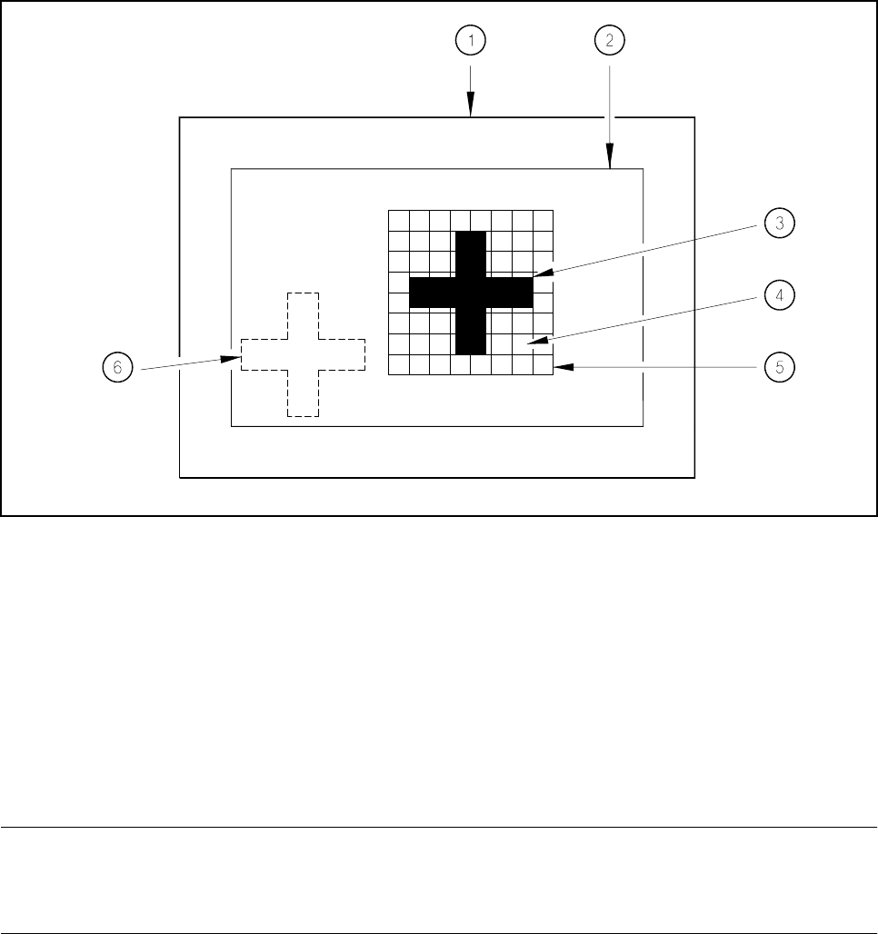
Fig. 5.2.1 Explanation of camera field of view, search area and template window
- Key to Fig. 5.2.1
1 Camera field of view 2 Search area, ≤ camera field of view
3 Reference fiducial (the fiducial is searched for in this area )
5 Template window 4 Moxel = pixel field, eg 16 x 16 pixels
(it contains the reference fiducial) 6 Fiducial which is to be searched for
The template window is moved over the search area in moxel steps. The gray scale values of each moxel of
the reference fiducial are calculated at this time. This reduced data structure will contain enough information
on the coarse structure and position of the reference fiducial.
NOTE
The search window should be as small as possible in order to keep the speed of searching high. On the other
hand the window should be large enough to allow the fiducial to be identified without ambiguity.
The 1-D pattern search procedure is used for precisely determining the pattern and position of the fiducial.
The fiducial image is broken up into rows and columns and the gray scale values in each row and column
added up. The next diagram illustrates this process using a double cross.
5 Vision Functions SIPLACE 80S-20/F4/F4-6/F5 User’s Manual
5.2 PCB Vision System Edition 03/98 from Software Version SR.404.xx
5 - 22 Line engineer
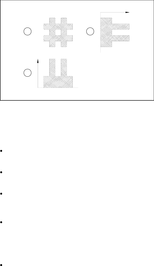
Fig. 5.2.2 Row and column profile of a double cross
- Key to Fig. 5.2.2
1Fiducial
2 Sum of the gray scale values in one column: column profile
3 Sum of the gray scale values in one row: row profile
The position of the fiducial is precisely determined from the horizontal and vertical profiles. After teaching
the fiducial structure parameters obtained are saved to the line computer.
The saved pattern is now tested. The gantry moves the PCB camera over the board to all 4 corners of the
search area (worst case). During this test the vision system must re-identify the fiducial four times.
Finally the coordinates of each individual fiducial (at least two) are manually added to the NU file or trans-
ferred from the CAD file to the NU file. In this way the coordinates and fiducial structure parameters for the
board which is to be inserted are defined as a pattern in the system.
During the placement process the fiducial parameters will then be determined once again using the 2-D
and 3-D image processing methods described above. The template window is moved moxel by moxel over
the search area searching for the best possible agreement of the gray scale values of the reference and
board search fiducials (correlation procedure). Maximum correlation is attained when the reference and
search fiducials agree.
Once the fiducial has been found, the 1-D pattern search process starts its very precise determination of
the shape and coordinates of the fiducial. The precise shape and coordinates of the fiducial are now deter-
mined in each case by applying the correlation procedure to the column and row profiles (see Fig. 5.2.2).
From the coordinates obtained in this way the location, skew and shear of the board are determined.
Reject fiducials (= ink dots) are also detected and evaluated using the methods described above.
1 2
3