80S-2080F480F4-680F5 User’s Manual.pdf - 第317页
5 Vision Functions SIPLACE 80S-20/F4/F4-6/F5 User’s Manual 5.6 Test Component Edition 03/98 from Software Version SR.404.xx 5 - 96 Line engine er Cross: white: Me asured b all candida tes whic h are defi ned in the packa…
SIPLACE 80S-20/F4/F4-6/F5 User’s Manual 5 Vision Functions
Edition 03/98 from Software Version SR.404.xx 5.6 Test Component
Line engineer 5 - 95
Crosshairs:
white: Results of position recognition -> x and y angles
Star:
white: Center of the component ->Position
Synthetic model representation at the lefthand edge of the video image:
Image: Model in pixel resolution
Points marked with red plus signs (+):
outside the circle:
Contrast < 0, ball is darker than the background
within the circle:
Contrast > 0, ball is lighter than the background
Points marked with yellow minus signs (-):
The difference between the plus and minus signs represents
the radial tolerance.
2. Ball-driven mode
See Section 5.6.4.14 from Page 5 - 109 for a definition of the measuring methods.
The method works with high precision and is thus suitable for precisely determining the position of all defined
balls. As a higher precision search, ball-driven mode will follow grid-driven mode.
This measurement method can be identified
– by the synthetic model being shown in pixel resolution at the lefthand edge of the video image,
– by there being a window around every ball (separate window) or
– by a window covering the entire component or over a defined row of balls (combined window) - this will
depend on the memory.
Procedure:
All of the balls defined in the package form file are surveyed. Geometric criteria are used here in the selection
of the window mode:
– If the separation of two balls is low (< 2 ball diameters) the combined window mode will be preferred.
– If the balls are relatively far apart the separate window mode will be selected. The default window mode is
the separate window mode.
Window:
dark blue: Over a single ball in each case (separate window)
Over a row or over all balls (combined window)
5 Vision Functions SIPLACE 80S-20/F4/F4-6/F5 User’s Manual
5.6 Test Component Edition 03/98 from Software Version SR.404.xx
5 - 96 Line engineer
Cross:
white: Measured ball candidates which are defined in the package form file.
Crosshairs:
white: Results of position recognition -> x and y angles
Star:
white: Position of the component
Synthetic ball model representation
in pixel resolution on the lefthand edge of the video image
A description will be found in the Grid-driven mode section.
5.6.4.5
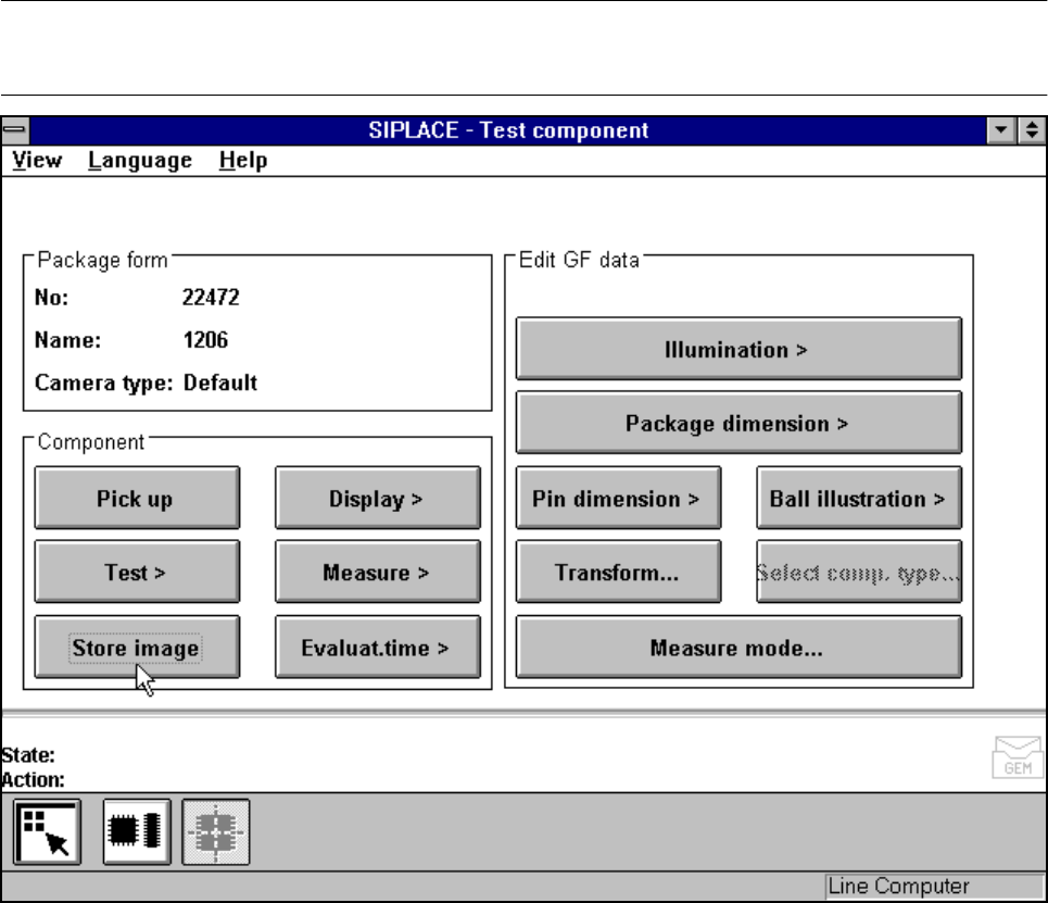
Store image
Option
NOTE
You cannot click on this option until a package form number has been loaded.
Fig. 5.6.16 Test component menu, Store image option
SIPLACE 80S-20/F4/F4-6/F5 User’s Manual 5 Vision Functions
Edition 03/98 from Software Version SR.404.xx 5.6 Test Component
Line engineer 5 - 97
This menu is used to store the generated video image as a file on the hard disk of the machine controller. The
file name and path are preset to:
C:\TMP\MVSBILD.MVS
For further analysis at Siemens AG, copy the file from the hard disk of the MVS controller onto a diskette and
send it to the AUT 5 Service Department.
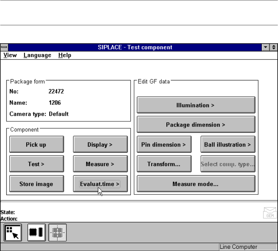
5.6.4.6
Analysis time
Option
NOTE
You cannot click on this option until a package form number has been loaded.
Fig. 5.6.17 Test component menu, Analysis time option
This option is used to display the analysis time for a selected component. Once you have activated the func-
tion, the following actions are started:
– The measuring procedure is activated.
– The video image appears on the screen
– The analysis time is overlaid.