80S-2080F480F4-680F5 User’s Manual.pdf - 第230页
SIPLACE 80S-20/F4/F4-6/F5 User’s Manual 5 Vision Functi ons Edition 03/98 from S oftware Version SR.404.xx 5.1 Overview of the Vision Sy stems in the SIPLACE 80S-20/F4/F4-6/F5 Mac hines Line engi neer 5 - 9 Fig. 5.1.6 Lo…
5 Vision Functions SIPLACE 80S-20/F4/F4-6/F5 User’s Manual
5.1 Overview of the Vision Systems in the SIPLACE 80S-20/F4/F4-6/F5 Machines Edition 03/98 from Software Version SR.404.xx
5 - 8 Line engineer
5.1.2 Vision Systems in the SIPLACE 80F
4
Placement Machine
The single gantry system of the SIPLACE 80F
4
machine (see Fig. 5.1.5, Page 5 - 8) is fitted with one revolver
placement head and one IC placement head. The revolver placement head is equipped with a camera system
for component position recognition (see Fig. 5.1.3, Page 5 - 6). The camera systems (up to two) for compo-
nent position recognition at the IC head are mounted on the machine base (see Fig. 5.1.6, Page 5 - 9).
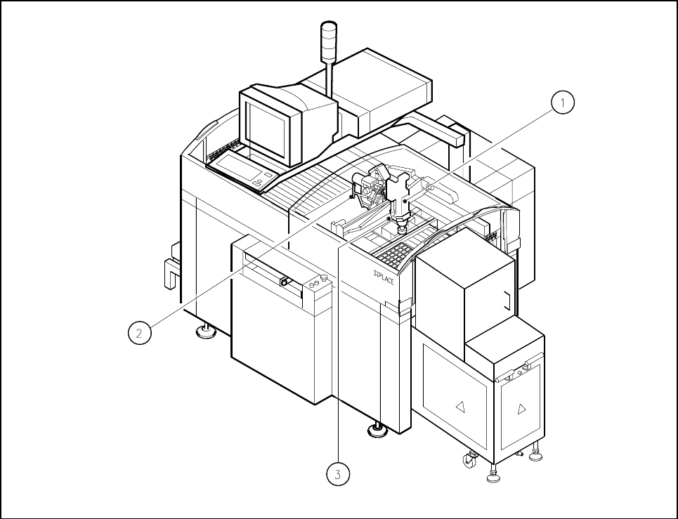
Fig. 5.1.5 Position of the placement heads and of the PCB vision system on the SIPLACE 80F
4
placement machine
- Key to Fig. 5.1.5
1 IC placement head 2 12x revolver placement head
3 PCB camera on the underside of the gantry
The 12-nozzle revolver placement head can be used to visually center and insert components up to 18.7 mm
x 18.7 mm in size.
The IC head and IC vision system can be used to visually center and insert components up to 55mm x 55mm
in size.
The FC vision system can be used to visually center components up to 20 mm x 20 mm.
The PCB position recognition camera system is located on the underside of the gantry. As a standard it cen-
ters board sizes from a minimum of 50 mm x 50 mm to a maximum of 460 mm x 460 mm, but with an optional
maximum of 508 mm x 460 mm. Board thickness may range between 0.5 mm and 3 mm.
SIPLACE 80S-20/F4/F4-6/F5 User’s Manual 5 Vision Functions
Edition 03/98 from Software Version SR.404.xx 5.1 Overview of the Vision Systems in the SIPLACE 80S-20/F4/F4-6/F5 Machines
Line engineer 5 - 9
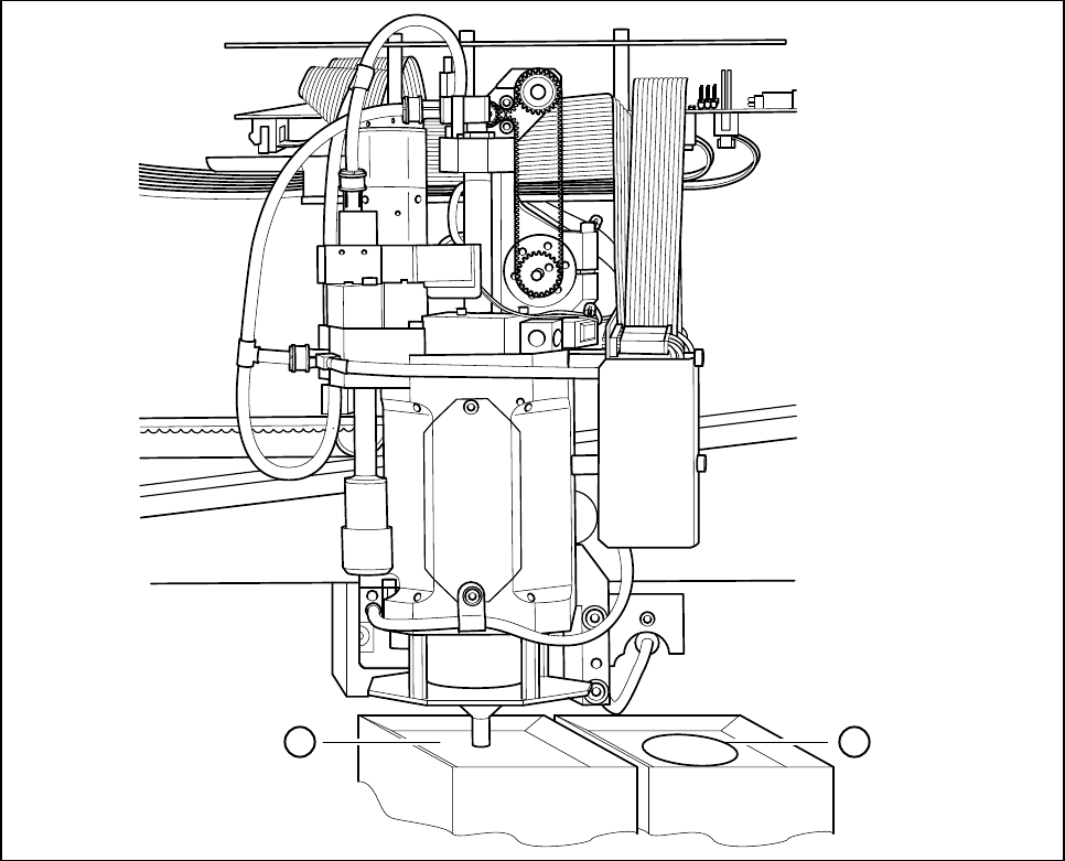
Fig. 5.1.6 Location of the component camera system for the IC placement head
- Key to Fig. 5.1.6
1 IC sensor system 2 FC (flip chip) sensor system
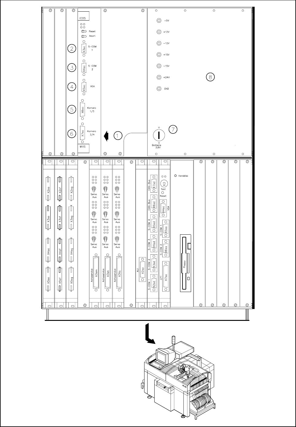
The evaluation unit (ICOS MVS system) which is accommodated in the machine’s control unit (see Fig. 5.1.7,
Page 5 - 10) processes and evaluates the signals from the PCB and component camera systems of the
12x revolver and IC placement heads. The deviations from the nominal values are used for determining cor-
rection values which are then used in the recalculation of the placement positions and the skew of the compo-
nents to be inserted.
- Key to Fig. 5.1.7
1 PCB and component evaluation unit of vision system 2 COM1
3 COM2 4 Screen connection
5 Camera connections 6 Camera connections
1 PCB camera 2 IC-head camera
3 Component camera, 12x revolver head 4 FC camera
7 Battery 8 Power supply unit
1 2
5 Vision Functions SIPLACE 80S-20/F4/F4-6/F5 User’s Manual
5.1 Overview of the Vision Systems in the SIPLACE 80S-20/F4/F4-6/F5 Machines Edition 03/98 from Software Version SR.404.xx
5 - 10 Line engineer
Fig. 5.1.7 Vision evaluation unit in the SIPLACE 80F
4
placement machine