80S-2080F480F4-680F5 User’s Manual.pdf - 第497页
9 Maintenance SIPLACE 80S-20/F4/F4-6/F5 User’s Manual 9.5 12x Revolver Head 10000 Edition 03/98 from Software Version SR.404.xx 9 - 48 9.5.1 Overview of Star Stations 1 - 12 Fig. 9.5.2 Overview of the functions of star s…
SIPLACE 80S-20/F4/F4-6/F5 User’s Manual 9 Maintenance
Edition 03/98 from Software Version SR.404.xx 9.5 12x Revolver Head 10000
9 - 47
9.5 12x Revolver Head 10000
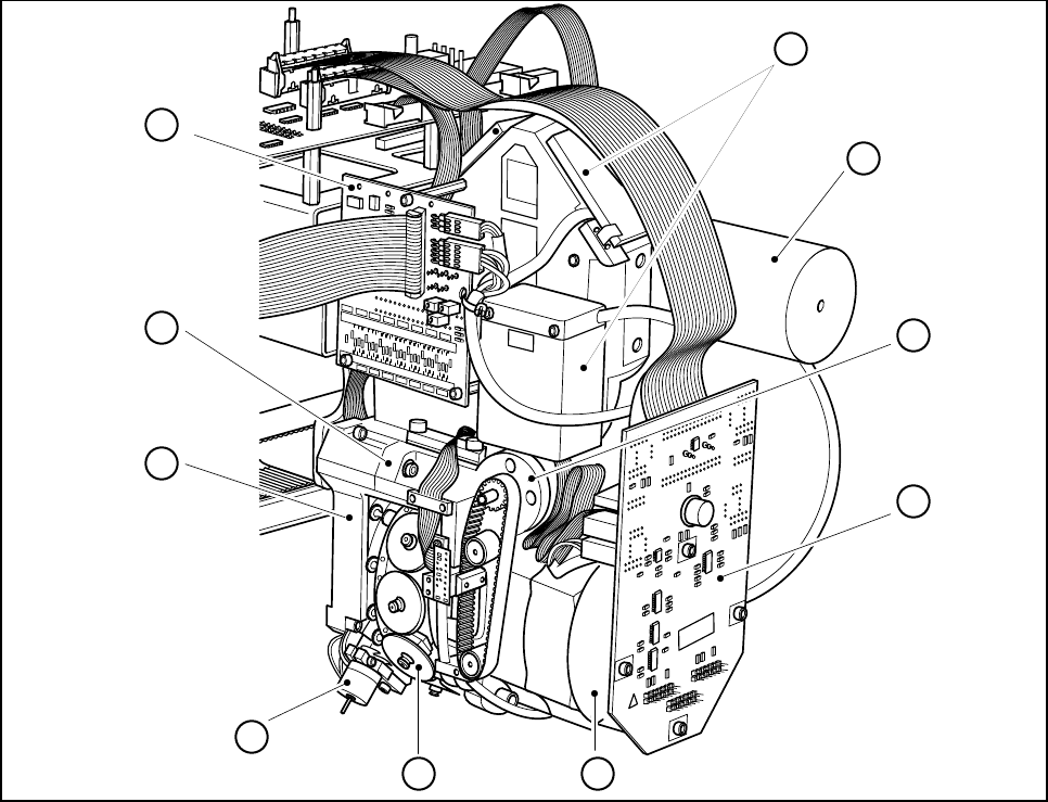
Fig. 9.5.1 12x revolver head, with cover removed
- Key to Fig. 9.5.1
1 Sleeves (12)
2 Motor for Eject valve actuator
3Back part
4Front part
5 Board for component illumination
6 Component camera with lens system and lighting
7Silencer
8 Z axis drive motor
9 Adapter board
10 Star drive
008
008
4
6
1
2
3
7
8
9
10
5
9 Maintenance SIPLACE 80S-20/F4/F4-6/F5 User’s Manual
9.5 12x Revolver Head 10000 Edition 03/98 from Software Version SR.404.xx
9 - 48
9.5.1 Overview of Star Stations 1 - 12
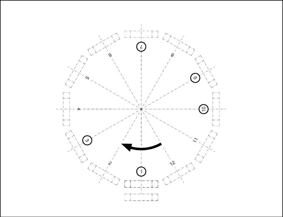
Fig. 9.5.2 Overview of the functions of star stations 1 -12
- Key to Fig. 9.5.2
1 Pick-up / place component
2 Star station with no function
3 Eject component
4 Star station with no function
5 Star station with no function
6 Star station with no function
7 Optical system of component vision system
8 Star station with no function
9 Rotate component
10 Location for sleeve removal
11 Star station with no function
12 Star station with no function

SIPLACE 80S-20/F4/F4-6/F5 User’s Manual 9 Maintenance
Edition 03/98 from Software Version SR.404.xx 9.5 12x Revolver Head 10000
9 - 49
9.5.2 Sleeve
NOTE
Do not touch the sleeve with your bare hands. You should wear white laboratory gloves when working on the
sleeve. In this way you will avoid damaging or soiling the cover disk or the encoder disk.
9.5.2.1 Removing the Sleeve
Tools and Consumables: white laboratory gloves
In the Main view menu click on the Gantry 1 functions or Gantry 2 functions menu.
In the Gantry functions menu click on the Go to service position button.
Click on the Revolver head functions menu.
Keep clicking on the Star step button until the desired sleeve is in the removal position - that is, Star
station 10 (see Fig. 9.5.2)
Turn the key-operated switch to the Unlock position.
Open the safety hoods.
Remove the selected sleeve from the segment.
In order to make a mechanically secure connection between sleeve and segment the sleeve latches with
its annular groove at the radial spring of the segment (Fig. 9.5.3, page 9 - 51). After a certain amount of
transition resistance is overcome the sleeve can be pulled easily off the segment.
NOTE
If you remove several sleeves, do not fail to make a note of the sleeves and their corresponding star position
numbers so that the sleeves can subsequently be replaced in accordance with the sleeve-nozzle configura-
tion.
Put the sleeves either in the storage case or onto a clean foam rubber mat.
9.5.2.2 Installing the Sleeve
Tools and Consumables: white laboratory gloves
Insert each sleeve in the star position intended for it.
Make sure that the sleeve latches into the segment (you should feel this).
In the Revolver head functions advance the star until all of the sleeves have been inserted.
Close die safety hoods.
Turn the key-operated switch into the Locked position.
Carry out a vacuum test on the sleeve (see Section 9.5.2.3)