80S-2080F480F4-680F5 User’s Manual.pdf - 第87页
SIPLACE 80S-20/F4/F4-6/F5 User’s Manual 2 Introduction and Basic Concepts Edition 03/98 from Software Version SR.404.xx 2.1 Display and Controls on the Machine 2 - 9 2.1.6 Switches on the Machine Fig. 2.1. 5 shows the po…
2 Introduction and Basic Concepts SIPLACE 80S-20/F4/F4-6/F5 User’s Manual
2.1 Display and Controls on the Machine Edition 03/98 from Software Version SR.404.xx
2 - 8
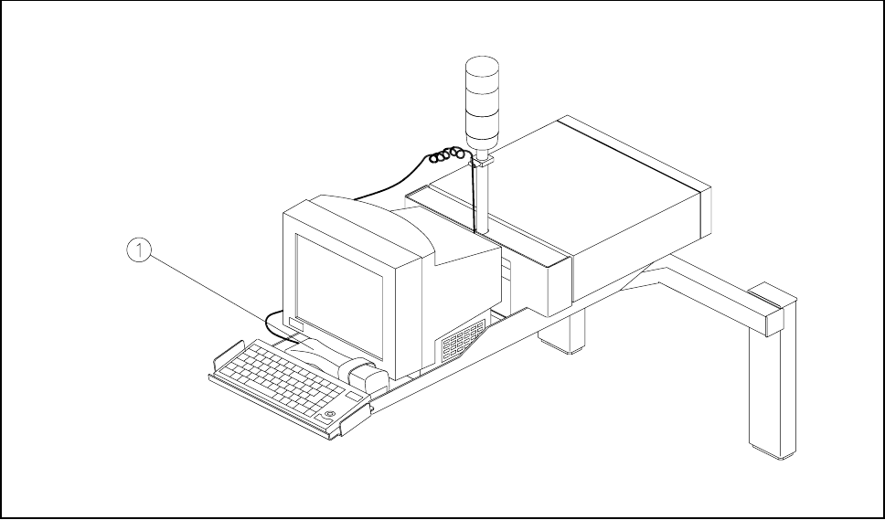
2.1.5 BAR CODE Reader (Option)
The bar code reader will help you, particularly under production conditions, to read quickly and reliably com-
ponent bar codes from component reels and track bar codes from the bar code strip on the machine. As each
data record is successfully read in, this is acknowledged by an acoustic signal.
Fig. 2.1.4 Bar code reader
- Key to Fig. 2.1.4
1 Bar code reader
SIPLACE 80S-20/F4/F4-6/F5 User’s Manual 2 Introduction and Basic Concepts
Edition 03/98 from Software Version SR.404.xx 2.1 Display and Controls on the Machine
2 - 9
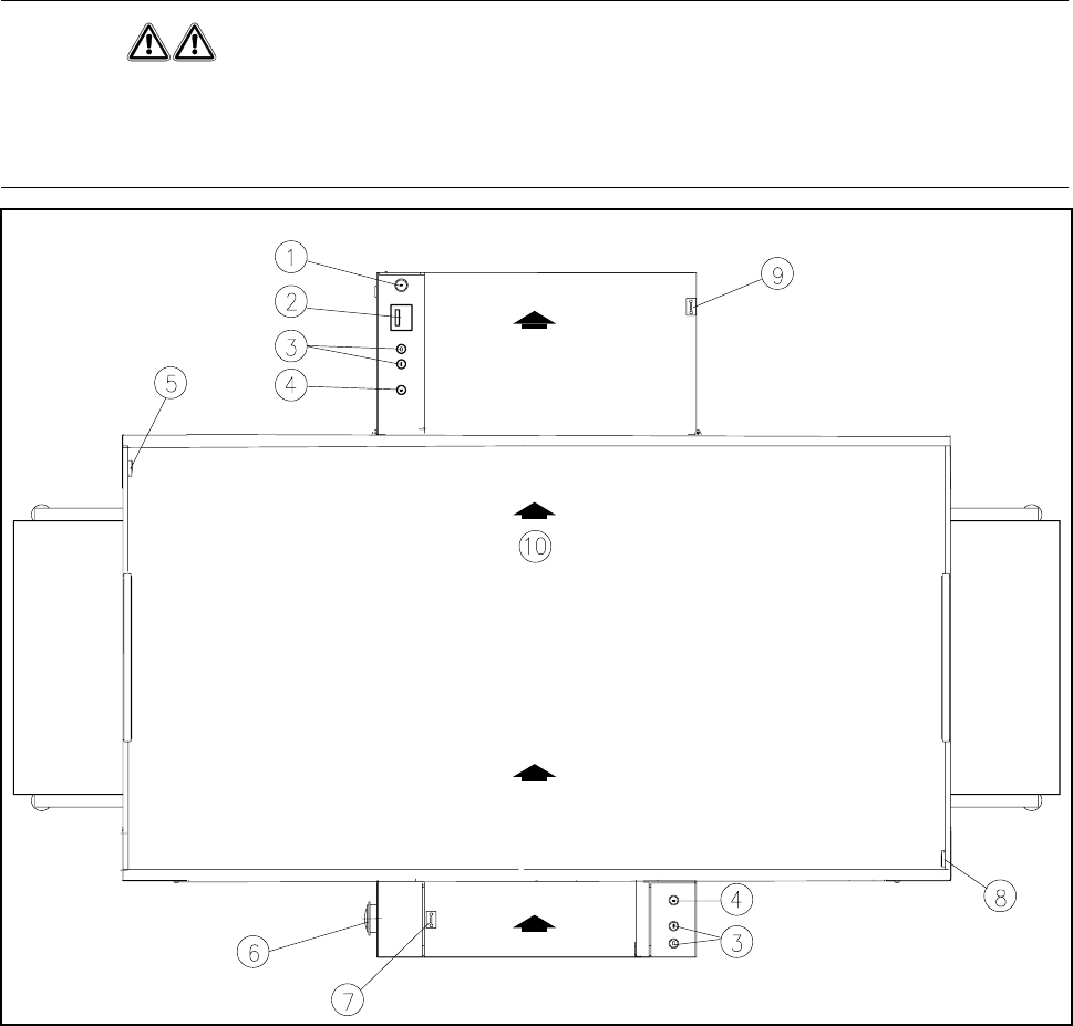
2.1.6 Switches on the Machine
Fig. 2.1.5 shows the position on the machine of the main switch, the cover switch, pushbuttons for start and
stop, the EMERGENCY STOP button, and the key-operated switch.
WARNING
Only appropriately qualified personnel are permitted to use the key-operated switch for servicing or mainte-
nance work. In all other cases the key must be kept secure against unauthorized access as otherwise the out-
come could be serious injury to the person or damage to the machine. .
Fig. 2.1.5 Position of the switches on the machine
- Key to Fig. 2.1.5
1 Key-operated switch 2 Components counter
3 Start and stop buttons 4 Emergency stop switch
5 Left cover switch 6 Main switch
7 Cover switch on cover of input belt 8 Right cover switch
9 Cover switch on cover of output belt 10 Transport direction
2 Introduction and Basic Concepts SIPLACE 80S-20/F4/F4-6/F5 User’s Manual
2.1 Display and Controls on the Machine Edition 03/98 from Software Version SR.404.xx
2 - 10
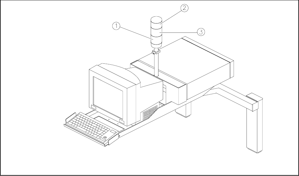
2.1.7 Main Fault Indicator
For each gantry there is a fault indicator light on the main fault indicator. The lower fault indicator light is for
gantry 1 and the top indicator light is for gantry 2.
Fig. 2.1.6 Main fault indicator
- Key to Fig. 2.1.6
1 Fault indicator lamp (white), gantry 1 (location 3/4) 2 Fault indicator lamp (white), gantry 2 (location 1/2)
3 Operating status lamp (green)
2.1.7.1 Functional Description
- Operating status lamp lights up continuously
The placement system is in service
- Operating status lamp flashes
The placement system is either waiting for a PCB on the input conveyor or is waiting until the output con-
veyor becomes free.
- The fault light flashes
One or more tracks of the gantry in question are empty. The machine will however work its way through
the remaining components.
- The fault light is continuously illuminated
A fault has occurred in the gantry in question. The machine has stopped.
- Both fault lights are continuously illuminated.
A fault has occurred affecting the entire machine. The machine has stopped.