80S-2080F480F4-680F5 User’s Manual.pdf - 第246页
SIPLACE 80S-20/F4/F4-6/F5 User’s Manual 5 Vision Functi ons Edition 03/98 from S oftware Version S R.404.xx 5.2 PCB Vision System Line engi neer 5 - 25 – Thicknes s (d) You shoul d ensure, par ticularly with tin fiduc ia…
5 Vision Functions SIPLACE 80S-20/F4/F4-6/F5 User’s Manual
5.2 PCB Vision System Edition 03/98 from Software Version SR.404.xx
5 - 24 Line engineer
Properties of the simple cross
– The informational content is somewhat lower than with the double cross
– Less space required in the layout than with the double cross.
– Less sensitive to high tin-coatings than with the double cross.
Dimensions of the fiducials:
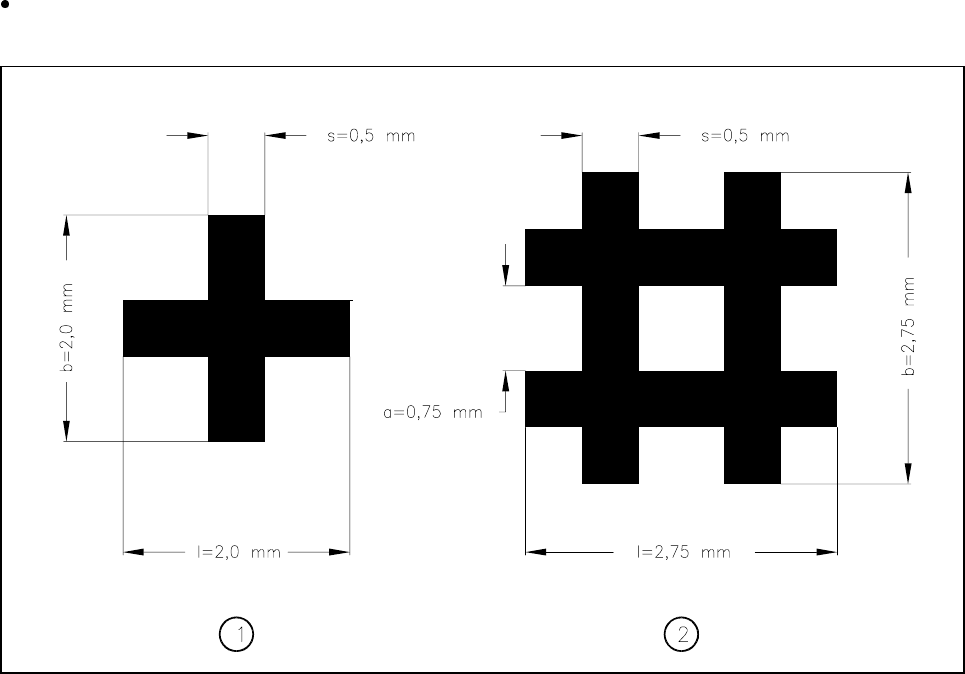
Simple and double crosses
Fig. 5.2.3 Simple and double crosses with ideal dimensions
- Key to Fig. 5.2.3
1 Simple cross 2 Double cross
The minimum dimensions for a fiducial in length (l) and width (b) depend on the line thickness (s) and on the
structure of the fiducial.
– Length (l) and width (b)
For the good recognizability of a fiducial, the length and the width should be at least 0.9 mm with the sim-
ple cross and 1.8 mm with the double cross. The ideal dimensions for the simple cross are 2.0 mm and for
the double cross 2.75 mm. Under normal circumstances length and width will be equal.
– Line thickness (s)
The line thickness may vary according to standard structure widths and in addition will also depend on the
type of fiducial. However, you should ensure that the line is at least 0.3 mm thick. The ideal line thickness
for both fiducial types is 0.5 mm.
– Line spacing (a)
Line spacing also depends on the type of fiducial. Under no circumstances should line spacing fall below
0.5 mm. With the double cross the ideal spacing will be 0.75 mm.

SIPLACE 80S-20/F4/F4-6/F5 User’s Manual 5 Vision Functions
Edition 03/98 from Software Version SR.404.xx 5.2 PCB Vision System
Line engineer 5 - 25
– Thickness (d)
You should ensure, particularly with tin fiducials, that a warpage of more than 1/10 of the structure width is
not exceeded. If this degree of warpage is exceeded then under certain circumstances the fiducial may not
be evenly illuminated. This would lead to variations in reflection characteristics and unwanted reflections.
Recognition of the fiducials will then no longer be assured.
Recommended fiducial dimensions
Evaluation of the fiducial shapes
With tinned structures and higher dimensional stability (a low degree of etching variation) full circles or full
squares may be regarded as very satisfactory fiducial shapes (the ratio of fiducial thickness to presoldering
thickness will be large!). If dimensional stability falls, the full circle should be preferred to the square.
As far as the fiducial shapes of simple and double cross are concerned, bright copper is advantageous as
long as oxidation has not advanced too far.
l Surface of the fiducials
Make sure that the surface of the fiducial is as level as possible and with little oxidation. Avoid wetting the
fiducial with solder-stop lacquer as this could result in lowering the contrast with the background or pro-
duce unwanted reflections. Similar effects occur with tinned fiducials as well.
l Contrast of the fiducials
To ensure that fiducial recognition is of a high quality select a high brightness contrast between the fiducial
and the base material; in other words, bright fiducials on a dark base material and vice versa. For example,
on a copper or tin background apply dark fiducials. In the case of ceramic substrates with a bright surface
and unsatisfactory reflective properties it is often helpful to precoat with a dark resistance material in order
to improve contrast characteristics.
l Number of fiducials
When using ceramic substrates and small boards it will usually be sufficient to apply two fiducials. How-
ever, with larger boards it is recommended that three fiducials be defined. The individual fiducials can vary
in structure. You can simplify the recognition procedure if you use the same structure for each fiducial.
Fiducial type
Simple cross Double cross
Range Ideal range Range Ideal range
Length (l) 0.9 mm (min) 2.0 mm 1.8 mm 2.75 mm
Width (b) 0.9 mm (min) 2.0 mm 1.8 mm 2.75 mm
Line thickness (s) 0.3 - 1.5 mm 0.5 mm 0.3 - 0.75 mm 0.5 mm
Line spacing (a) — — 0.5 mm (min) 0.75 mm
Thickness (d) < 1/10 of the structure width < 1/10 of the structure width
Tab. 5.2.2 Recommened fiducial dimensions

5 Vision Functions SIPLACE 80S-20/F4/F4-6/F5 User’s Manual
5.2 PCB Vision System Edition 03/98 from Software Version SR.404.xx
5 - 26 Line engineer
– Correction with two fiducials x-position
y-position
PCB skew
– Correction with three fiducials: ideally the straight lines which each pass through the centers of two
fiducial will be parallel with the x and y axes
x-position
y-position
PCB skew
Shear
Warpage of PCB in the x direction
Warpage of PCB in the y direction
NOTE
You should never position 3 fiducials so that they are located on a straight line.
Spacing between the fiducials
You may locate the fiducials at any point on the board. However, it is a good idea to space the fiducials as
far apart as possible on the two axes. The further apart the fiducials are from one another, the more accu-
rate optical position and angle recognition will be.