80S-2080F480F4-680F5 User’s Manual.pdf - 第316页
SIPLACE 80S-20/F4/F4-6/F5 User’s Manual 5 Vision Functi on s Edition 03/98 from S oftware Version SR.404.xx 5.6 Test Component Line engi neer 5 - 95 Crossh airs: white : Res ults of po sition r ecognit ion -> x an d y…
5 Vision Functions SIPLACE 80S-20/F4/F4-6/F5 User’s Manual
5.6 Test Component Edition 03/98 from Software Version SR.404.xx
5 - 94 Line engineer
Optical measurement of BGAs and flip-chips with the 80F
4
, 80F
4
-6 or 80F
5
placement machines:
The crosshairs indicate the position of the component in the camera coordinates system. The outline of the
component will be emphasized by the use of color.
The measured values represent geometric component parameters such as
– Position in the camera coordinates system
– Rotation angle
– Maximum offset of the balls in x and y directions
– Factor for the quality of measurement
1. Grid-driven mode
See Section 5.6.4.14 from Page 5 - 109 for a definition of the measuring methods.
Grid-driven mode works with preset pattern tolerances and is therefore to be regarded as the first measure-
ment step in the optical surveying of BGAs and flip-chips. To ascertain the approximate position it will be ade-
quate to measure just a few connections.
The number of balls to be measured and the pattern tolerances define the size of the search window. The
rough position and the skew of the component are determined in corners mode - in other words, a search win-
dow size is defined for each corner of the component. This measurement method can be identified
– by the synthetic model being shown in pixel resolution at the lefthand edge of the video image, and
– by the 4 windows at the corners of the component.
Procedure:
– The algorithm defines 4 dark blue corner windows on the basis of the pattern tolerances and the balls
defined in the package form file. The default search value is 5 balls.
– A detection algorithm runs with the aim of detecting all balls corresponding to this type. Those found will be
marked with light blue crosses.
– The balls defined in the package form file are determined by the search algorithm. The balls found are
marked with a white outline. If defined balls are not found an error message will appear on the screen.
– From these data the rough position and the skew of the component are determined. The measured posi-
tion of the component is marked with white crosshairs.
Rectangle:
dark blue: 4 search windows, depending on the pattern tolerances and
the number of balls
Cross:
white: Ball model candidates found
Overlays:
white: Balls found which are defined in the package form file
SIPLACE 80S-20/F4/F4-6/F5 User’s Manual 5 Vision Functions
Edition 03/98 from Software Version SR.404.xx 5.6 Test Component
Line engineer 5 - 95
Crosshairs:
white: Results of position recognition -> x and y angles
Star:
white: Center of the component ->Position
Synthetic model representation at the lefthand edge of the video image:
Image: Model in pixel resolution
Points marked with red plus signs (+):
outside the circle:
Contrast < 0, ball is darker than the background
within the circle:
Contrast > 0, ball is lighter than the background
Points marked with yellow minus signs (-):
The difference between the plus and minus signs represents
the radial tolerance.
2. Ball-driven mode
See Section 5.6.4.14 from Page 5 - 109 for a definition of the measuring methods.
The method works with high precision and is thus suitable for precisely determining the position of all defined
balls. As a higher precision search, ball-driven mode will follow grid-driven mode.
This measurement method can be identified
– by the synthetic model being shown in pixel resolution at the lefthand edge of the video image,
– by there being a window around every ball (separate window) or
– by a window covering the entire component or over a defined row of balls (combined window) - this will
depend on the memory.
Procedure:
All of the balls defined in the package form file are surveyed. Geometric criteria are used here in the selection
of the window mode:
– If the separation of two balls is low (< 2 ball diameters) the combined window mode will be preferred.
– If the balls are relatively far apart the separate window mode will be selected. The default window mode is
the separate window mode.
Window:
dark blue: Over a single ball in each case (separate window)
Over a row or over all balls (combined window)
5 Vision Functions SIPLACE 80S-20/F4/F4-6/F5 User’s Manual
5.6 Test Component Edition 03/98 from Software Version SR.404.xx
5 - 96 Line engineer
Cross:
white: Measured ball candidates which are defined in the package form file.
Crosshairs:
white: Results of position recognition -> x and y angles
Star:
white: Position of the component
Synthetic ball model representation
in pixel resolution on the lefthand edge of the video image
A description will be found in the Grid-driven mode section.
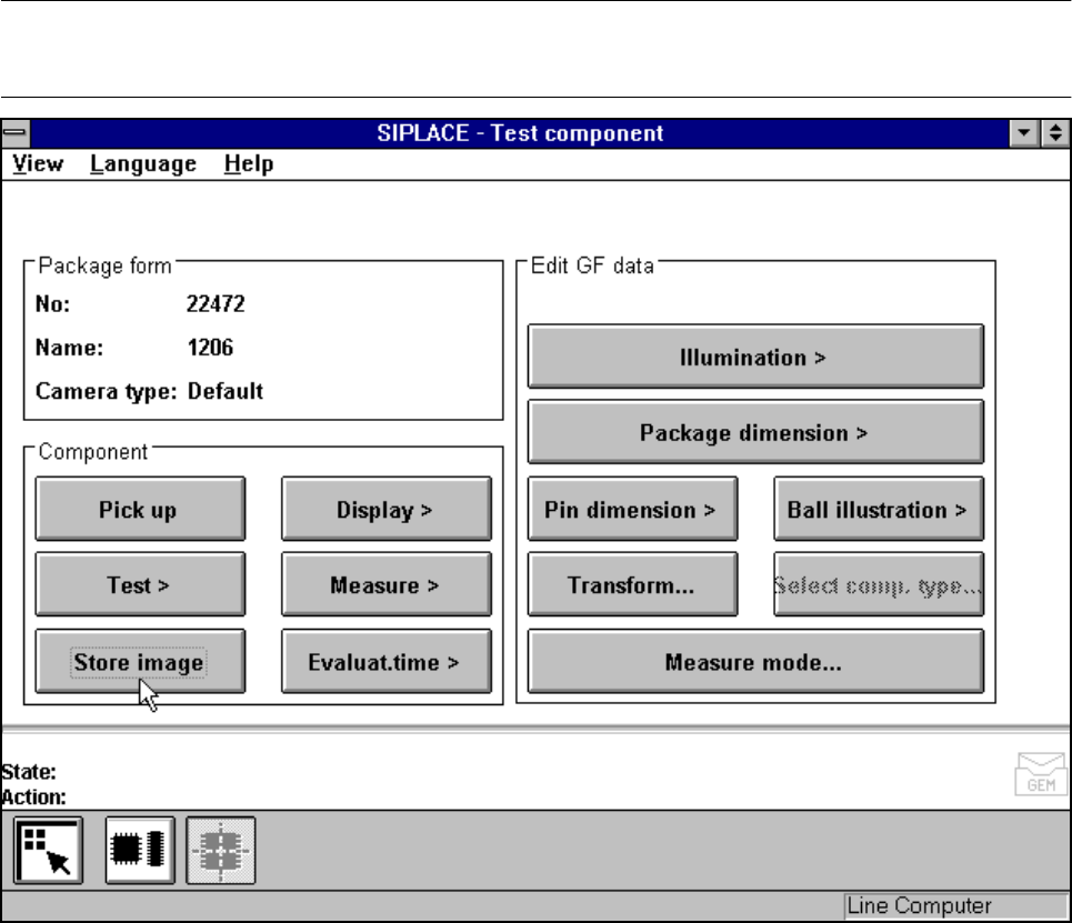
5.6.4.5
Store image
Option
NOTE
You cannot click on this option until a package form number has been loaded.
Fig. 5.6.16 Test component menu, Store image option