80S-2080F480F4-680F5 User’s Manual.pdf - 第360页
SIPLACE 80S-20/F4/F4-6/F5 User’s Manual 5 Vision Functi on s Edition 03/98 from S oftware Version SR.404.xx 5.7 Guidelines for Describing Package Form s Line engi neer 5 - 139 5.7.7.5 Testing Illumination Settings You ca…
5 Vision Functions SIPLACE 80S-20/F4/F4-6/F5 User’s Manual
5.7 Guidelines for Describing Package Forms Edition 03/98 from Software Version SR.404.xx
5 - 138 Line engineer
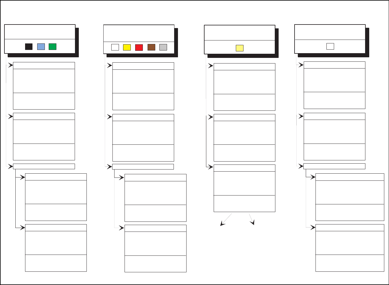
Fig. 5.7.10 Illumination parameters for other components at the IC head camera
Adjusting the illum ination of other com ponents
Light and dull body
( w hite, yellow , red, brow n, grey,
m e ta llic d u ll )
Ceram ic body
Dark and dull body
( black, blue, green )
R e fle c tiv e b o d y
(independently of color and m aterial)
D u ll le a d s
fla t: 1 0 0
middle: 30
steep: 40
Visual separation betw een leads
and body is not possible.
Illum inate body and leads equally.
M easure outline.
S h in y le a d s
C lear separation
betw een leads
and body.
D u ll le a d s
fla t: 2 5 5
m iddle: 90
steep: 0
S h in y le a d s
1. Illum inate body and leads equally.
M easure outline.
2. Trick: U se flat and m iddle levels to
bring leads im age to saturation.
M easure.
C lear separation
betw een leads
and body.
for variant 2:
fla t: 1 6 0
m iddle: 60
steep: 0
C lear separation
betw een leads
and body.
C lear separation
betw een leads
and body.
J-Lead ( PLC C ), convex-type leads
G u llw in g le a d s ( S O , Q F P )
D u ll le a d s
S h in y le a d s
C lear separation
betw een leads
and body.
C lear separation
betw een leads
and body.
J-Lead ( PLC C ), convex-type leads
G u llw in g le a d s ( S O , Q F P )
fla t: 9 0
middle: 40
steep: 10
fla t: 2 0 0
middle: 30
steep: 5
C lear separation
betw een leads
and body.
C lear separation
betw een leads
and body.
O ther lead shapes
D u ll le a d s
Visual separation betw een leads
and body is not generally possible.
S h in y le a d s
Leads:
O u tlin e :
M easuring m ethod:
Visual separation betw een leads
and body is not possible.
Illum inate body and leads equally.
M easure outline.
Visual separation betw een leads
and body is not possible. M easure
outline or lead tips. Leads are
outside the body.
J-Lead ( PLC C ), convex-type leads
G u llw in g le a d s ( S O , Q F P )
O ther lead shapes
C onvex-type leads
O ther lead shapes
Visual separation betw een leads
and body is not generally possible.
Illum inate body and leads equally.
M easure outline.
Illum ination level B rightness
fla t: 1 2 0 - 1 4 0
m iddle: 40 - 60
steep: 0 - 10
fla t: 9 0
m iddle: 90
steep: 5 - 10
fla t: 9 0
middle: 40
steep: 10
fla t: 2 0 0
middle: 30
steep: 5
Visual separation betw een leads
and body is not generally possible.
Leads:
O u tlin e :
M easuring m ethod:
fla t: 1 2 0
m id d le : 4 0
steep: 10 - 20
fla t: 1 2 0
m id d le : 4 0
steep: 0 - 10
fla t: 0
m id d le : 0
steep: 10 - 20
fla t: 0
m id d le : 0
steep: 20 - 40
fla t: 0
middle: 0
steep: 25
fla t: 1 0 0
middle: 30
steep: 40
fla t: 1 6 0
m iddle: 60
steep: 0
flat: 150 - 255
m iddle: 60 - 120
steep: 0

SIPLACE 80S-20/F4/F4-6/F5 User’s Manual 5 Vision Functions
Edition 03/98 from Software Version SR.404.xx 5.7 Guidelines for Describing Package Forms
Line engineer 5 - 139
5.7.7.5 Testing Illumination Settings
You can set the illumination parameters by calling the ’Illumination’ option (see Section 5.6.4.8, Page 5 - 101).
Using the 'Measure Component Option' you can then measure the component and check your settings with
the aid of the measurement results.
Proceed as follows to test your illumination setting:
Using the illumination values suggested in Figures 5.7.9 or 5.7.10 carry out measurement. Measurement
should run through successfully.
For each level reduce the set brightness level by 50 %.
Measurement should run through successfully.
For each level raise the set brightness level by 50 %.
Measurement should run through successfully.
If you are not successful with the above procedure, proceed as follows:
Starting with the suggested illumination value, increase the brightness of each individual illumination level
for as long as measurement is still successful.
Find this upper limit value for each individual illumination level in turn.
Starting with the suggested illumination value, decrease the brightness of each individual illumination level
for as long as measurement is still successful. Find this lower limit value for each individual illumination
level in turn.
Determine the average value of the upper and lower limit values. This will be the optimum illumination
value.
Example of an illumination test:
– Settings from the diagram:
flat: 170
middle: 60
steep: 5
– Measure the component. Measurement is successful.
– Reduce setting values by 50%.
flat: 85
middle: 30
steep: 2
– Increase setting values by 50%.
flat: 255
middle: 90
steep: 8
– Measure the component. Measurement is successful.
– Reset the settings to the suggested values:
flat: 170
middle: 60
steep: 5
¬ optimum setting

5 Vision Functions SIPLACE 80S-20/F4/F4-6/F5 User’s Manual
5.7 Guidelines for Describing Package Forms Edition 03/98 from Software Version SR.404.xx
5 - 140 Line engineer
5.7.7.6 General Information on Setting Illumination Values
– As a rule it is better to overilluminate the component than to underilluminate it. A saturated image is prefer-
able to a low-contrast image.
– Optimum illumination is attained when only the leads are imaged and the component body is not shown.
– If you cannot clearly separate the image of the component body from the leads, we recommend to illumi-
nate body and leads equally and then to measure the outline.
5.7.8 Setting the Components Illumination at the 6x Revolver Head
Camera (Standard vision system)
5.7.8.1 General Information on Illumination Methods
The idea of illumination setting is to obtain an image of the leads of a component which is as high-contrast as
possible. At the same time it is also important to suppress representation of the body of the component.
These instructions are intended to help you find the best possible illumination parameters. This, however,
does not imply that you rigidly comply with the values specified in these instructions. The way you should pro-
ceed is first to follow these instructions and then to adjust the parameters yourself where necessary. It may
well be that you come across one or other component the leads of which are better illuminated using values
different to the ones suggested in these instructions.
The illumination system comprises three different illumination levels. The intensities can be programmed indi-
vidually. By using the individual illumination levels one at a time or in combination with one another you can
adapt the illumination to suit a wide range of components.
Flat illumination level
The flat illumination level is used for illuminating BGAs, µBGAs, flip-chips, J-lead components (PLCC), Melfs
and components with convex-type leads. It tends to emphasize body and lead edges. It is, however, less suit-
able for displaying bright component bodies and ceramic components.
Steep illumination level
The main application for the steep illumination level is for reflective leads, ceramic components and bright
component bodies. It is less suitable for reflective component bodies, flip-chips or µBGAs.
NOTE
Most components will require a combination of these three illumination levels to achieve optimum illumination.
Using
one
illumination level will only be successful in exceptional cases.