80S-2080F480F4-680F5 User’s Manual.pdf - 第610页
SIPLACE 80S-20/F4/F4-6/F5 User’s Manual 11 Station Extensions/Options Edition 03/98 from Software Version SR.404.xx 11.3 PCB Barc ode 11 - 13 11.3 PCB Barco de 11.3.1 Overview The PCB ba rcode can be read fr om the un de…
11 Station Extensions/Options SIPLACE 80S-20/F4/F4-6/F5 User’s Manual
11.2 Nozzle Changer for IC Head (ICPW20) Edition 03/98 from Software Version SR.404.xx
11 - 12
SIPLACE 80S-20/F4/F4-6/F5 User’s Manual 11 Station Extensions/Options
Edition 03/98 from Software Version SR.404.xx 11.3 PCB Barcode
11 - 13
11.3 PCB Barcode
11.3.1 Overview
The PCB barcode can be read from the underside (solder side) or from the top side (insertion side) of a board.
If the bar code is placed on the top side of a board the reading head will be mounted in such a way that the
reading beam of the barcode reader hits the board from above.
If the bar code is located on the underside of a board, the reading head will be mounted in such a way that the
reading beam of the barcode reader hits the board from below.
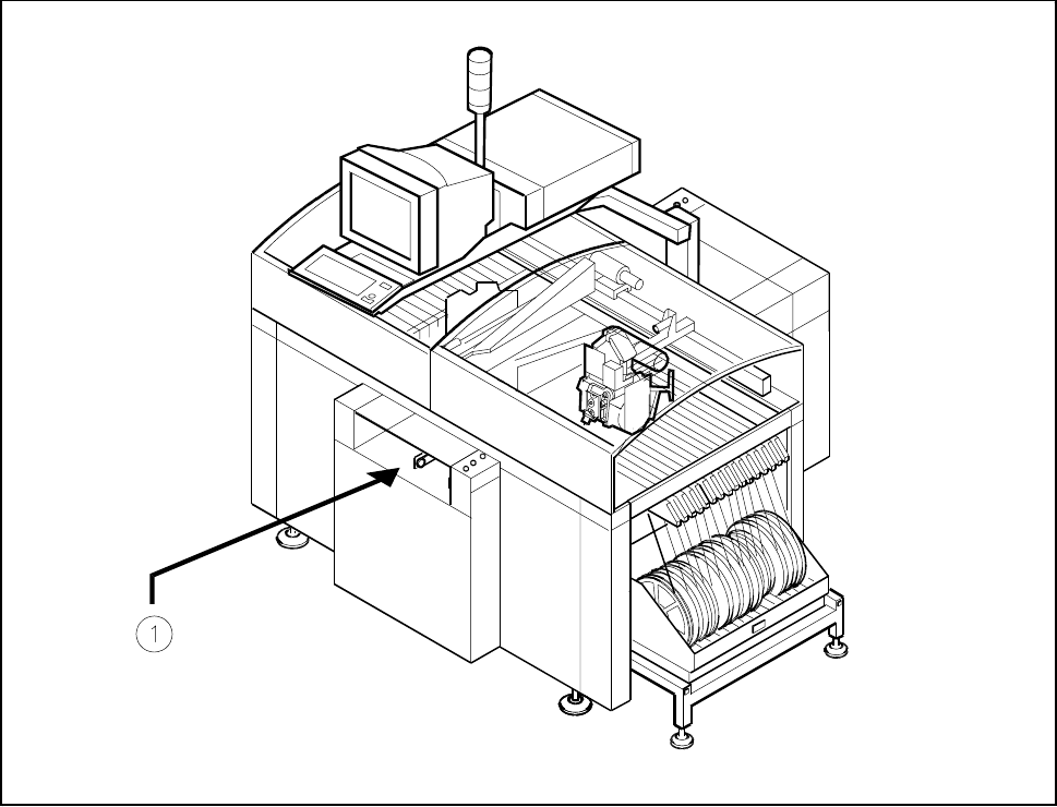
Fig. 11.3.1 Location where the PCB barcode reader is installed
Key to Fig. 11.3.1
1 Location of PCB barcode reader (can be fitted on top or below)

11 Station Extensions/Options SIPLACE 80S-20/F4/F4-6/F5 User’s Manual
11.3 PCB Barcode Edition 03/98 from Software Version SR.404.xx
11 - 14
11.3.2 Notes on Safety
CAUTION
The radiant power of the barcode reader‘s scanning beam is less than 1mW. This means that the barcode
reader conforms to laser class 2 and, according to DIN EN 60825-1, requires no special safety equipment or
protective measures. NEVER look into the laser beam. There is also a safety circuit that switches off the laser
diode if the polygon wheel stops or turns too slowly.
11.3.3 How It Works
The barcode reader is a reading device which registers and decodes data presented in the form of bar-cod-
ing. The barcode reader consists of the reading head and the decoder.
The laser diode which is built into the reading head creates a beam of monochrome red light. This is focussed
by a lens and deflected by a rotating polygonal mirror wheel. The signals reflected from the barcoded base
are registered by a photodiode and amplified. This train of electrical impulses which reproduces the sequence
of dark-to-light transitions in the base is then routed to an electronic evaluation device, the decoder.
The decoder consists of two parts: a rapid signal conditioning unit and a processing unit which decodes the
signals and converts them into ASCII format. The data are then routed to a serial interface for further process-
ing.
11.3.4 Parametrization and Adjustment
WARNING
Only personnel who have been trained at Siemens training center for SMD placement machines should be
permitted to carry out parametrization of the barcode reader.
Before a barcode is actually read, the barcode reader must know what kind of code is to be read and how
much data information (number of places) is contained in that code. The barcode reader is furnished with this
information via parametrization. From the structure of the defined code and the number of places it has, the
barcode reader can then calculate the precise number of lines and blanks.