80S-2080F480F4-680F5 User’s Manual.pdf - 第565页
10 Component Handling SIPLACE 80 S20/F4/F4-6/F 5 User’s Manual 10.3 Component Tables Edition 03/98 from Software Version SR.404.xx 10 - 12 Open the horizontal tensione r 7. Carefull y raise the comp onent table us ing th…
SIPLACE 80 S20/F4/F4-6/F5 User’s Manual 10 Component Handling
Edition 03/98 from Software Version SR.404.xx 10.3 Component Tables
10 - 11
10.3 Component Tables
10.3.1 Function
The SIPLACE 80S-20/F
4
-/F
4
-6/F
5
placement machines are equipped with changeable component tables.
These component tables can be changed with relatively little effort.
10.3.2 Changing Component Tables
10.3.2.1 Tools Required
10.3.2.2 Removal
WARNING
When you change the component table, always follow the sequence for removing the plugs from the commu-
nication unit and then connecting them again as described below. If you do not follow the specified order,
faults may occur in the component table.
WARNING
Move the portal out of the range of the component table over the PCB transport. This will prevent the possibil-
ity of a head crash.
DANGER
Press the emergency stop button. The gantry axes are switched off and isolated.
This will prevent the gantries starting up accidentally, thus preventing the associated risk of injury or damage.
Remove the plugs from the power supply for the component table.2.
Remove the communication plug 1.
If necessary, remove the connector for the compressed air supply to the component table 3.
Push the platform truck under the component table (A).
Loosen the two hexagon socket head screws for fixing the component table 5.
From item number
Hexagon socket spanner, set
Component table platform truck 00123141-01
10 Component Handling SIPLACE 80 S20/F4/F4-6/F5 User’s Manual
10.3 Component Tables Edition 03/98 from Software Version SR.404.xx
10 - 12
Open the horizontal tensioner 7.
Carefully raise the component table using the platform truck until the centering pins
«
are outside the hole
s.
Then pull out the component table.
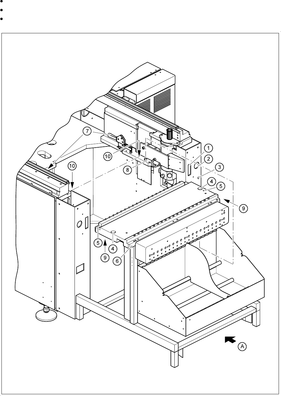
Fig. 10.3.1 Removal of the component table

SIPLACE 80 S20/F4/F4-6/F5 User’s Manual 10 Component Handling
Edition 03/98 from Software Version SR.404.xx 10.3 Component Tables
10 - 13
- Key to Fig. 10.3.1
10.3.2.3 Installation
Make sure that the contact surfaces of the component table and machine are clean (
9
and 10).
Pick up a component table with the lifting truck and raise the component table until it will not catch any-
where while being slid into the machine.
Carefully push the component table into the machine until the centering pin locating holes on the compo-
nent table are above the centering pins (4 and 8).
Carefully lower the component table until the component table rests on the machine base mounting.
Close the clamping levers (7).
Then plug in the flat plug for the communication signals.
Insert and tighten the two hexagon socket head screws
5
.
Plug in the round power supply plug.
Close the protective covers.
Release the EMERGENCY-STOP button.
1
Connection for the communication interface
2 Connection for the power supply to the component table
3
Compressed air connection
4
Holes for the centering pins
5 Hexagon socket head screws for fixing the component table
6
Supporting surface for the component table
7
Horizontal tensioner
8
Centering pins
9 Contact surfaces for the component table
10 Contact surfaces for the machines
A Push in the component table platform truck