80S-2080F480F4-680F5 User’s Manual.pdf - 第170页
SIPLACE 80S- 20/F4/F4-6 User’s Manual 4 Single Functions Edition 07/97 from Software Version SR.403.xx 4.2 Single Functions, Gantry with 12x Revolver Head 4 - 5 4.2 Single Functi ons, Gantry with 12x Revolver Head NOTE W…

4 Single Functions SIPLACE 80S-20/F4/F4-6 User’s Manual
4.1 Overview Edition 07/97 from Software Version SR.403.xx
4 - 4
4.1.1 General Comments
Single functions comprise gantry functions and transport functions.
Single functions are used for carrying out particular actions following a fatal error and also for setting up and
testing the machine. Single functions make it possible to control various function modules in a defined man-
ner.
The functions covered in this chapter Chapter 4 are described for the SIPLACE 80F
4
or 80F
4
-6, but they also
apply to the SIPLACE 80S-20. The only difference is that the gantry functions of the SIPLACE 80F
4
include
additional IC head and wafflepack changer functions.
WARNING
Single functions may only be used by appropriately qualified and trained personnel since improper handling
can result in injury to the person and / or damage to the machine.
SIPLACE 80S-20/F4/F4-6 User’s Manual 4 Single Functions
Edition 07/97 from Software Version SR.403.xx 4.2 Single Functions, Gantry with 12x Revolver Head
4 - 5
4.2 Single Functions, Gantry with 12x Revolver Head
NOTE
With travel functions of the x or y axis the machine cover must be closed and to execute the function the start
button must be pressed. The gantries will in every case travel only at slow speed.
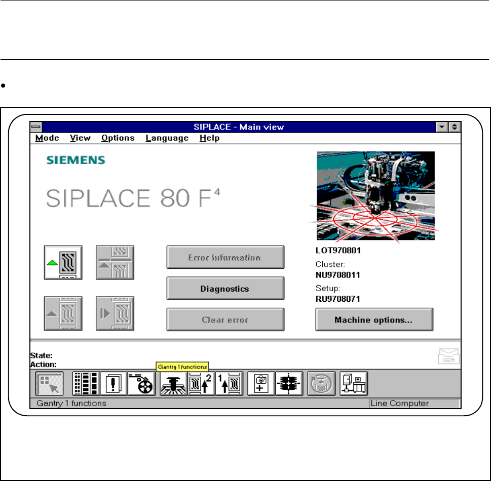
In main view click on the symbol button for Gantry functions.
Fig. 4.2.1 Gantry functions
F
4 Single Functions SIPLACE 80S-20/F4/F4-6 User’s Manual
4.2 Single Functions, Gantry with 12x Revolver Head Edition 07/97 from Software Version SR.403.xx
4 - 6
4.2.1 Gantry Functions
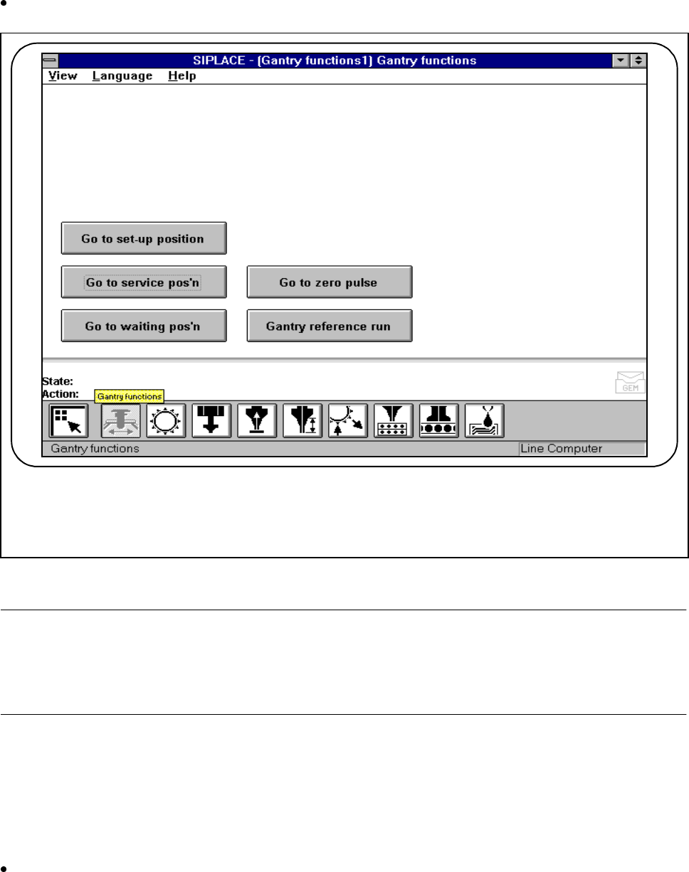
In the Gantry functions screen click on the symbol button for Gantry functions.
Fig. 4.2.2 Gantry functions
NOTE
All travel functions of the main axes (x and y) must be launched using the start button. The screen message
’Please press the start button’ which follows the menu item ’Action’ in the main menu will ask you to press the
start button. If the cover is not closed, another screen message will ask you to close the covers.
4.2.1.1 Go to set-up position
In the set-up position, the gantry is in a position in which the feeders can be unloaded and retooled. At this
time, the gantry is located in the center of the machine.
Click on the Go to set-up position button and then press the Start button whenever you are prompted to
do so. The gantry will travel to the set-up position.
F