80S-2080F480F4-680F5 User’s Manual.pdf - 第536页
SIPLACE 80S-20/F4/F4-6/F5 User’s Manual 9 Maintenance Edition 03/98 from S oftware Version SR.404.xx 9.7 6x Revolver Head (80 00) 9 - 87 – To rem ove the val ve plunge r, it has to be in star position 1. You als o have t…
9 Maintenance SIPLACE 80S-20/F4/F4-6/F5 User’s Manual
9.7 6x Revolver Head (8000) Edition 03/98 from Software Version SR.404.xx
9 - 86
9.7.6 Cleaning Vacuum/Forced Air Valves
9.7.6.1 Removing the Valve Plunger
Position the gantry concerned, with the revolver placement head over the PCB conveyor.
Switch off the placement system and disconnect the power supply.
Disconnect the compressed air supply.
Starting from the middle remove several feeders from the components changeover table.
Carefully push the gantry out to the stop by hand.
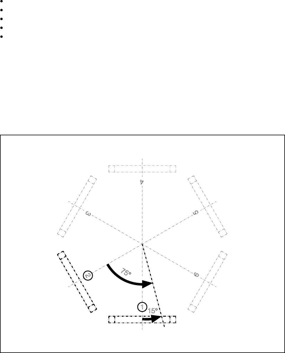
Depending on the valve adjustment drive responsible for prompting the error message you have to turn the
star by a certain angle to be able to remove and to clean the faulty valve:
Fault prompted by the ’pick-up/place’ valve adjustment drive
This valve adjustment drive is situated in star station 1 (see pos. 1, Fig. 9.7.8). Using your fingers, carefully
turn the star 15° counter-clockwise. 15° corresponds to a quarter turn of the star.
Fault prompted by the ’reject’ valve adjustment drive
This valve adjustment drive is situated in star station 3 (see pos. 3, Fig. 9.7.8). Using your fingers, carefully
turn the star 75° counter-clockwise. 75° corresponds to one and a half turns of the star.
Fig. 9.7.8 Positioning the star for valve plunger removal
- Key to Fig. 9.7.8
1 Position of the ’pick-up/place’ valve adjustment drive 3 Position of the ’reject’ valve adjustment drive
SIPLACE 80S-20/F4/F4-6/F5 User’s Manual 9 Maintenance
Edition 03/98 from Software Version SR.404.xx 9.7 6x Revolver Head (8000)
9 - 87
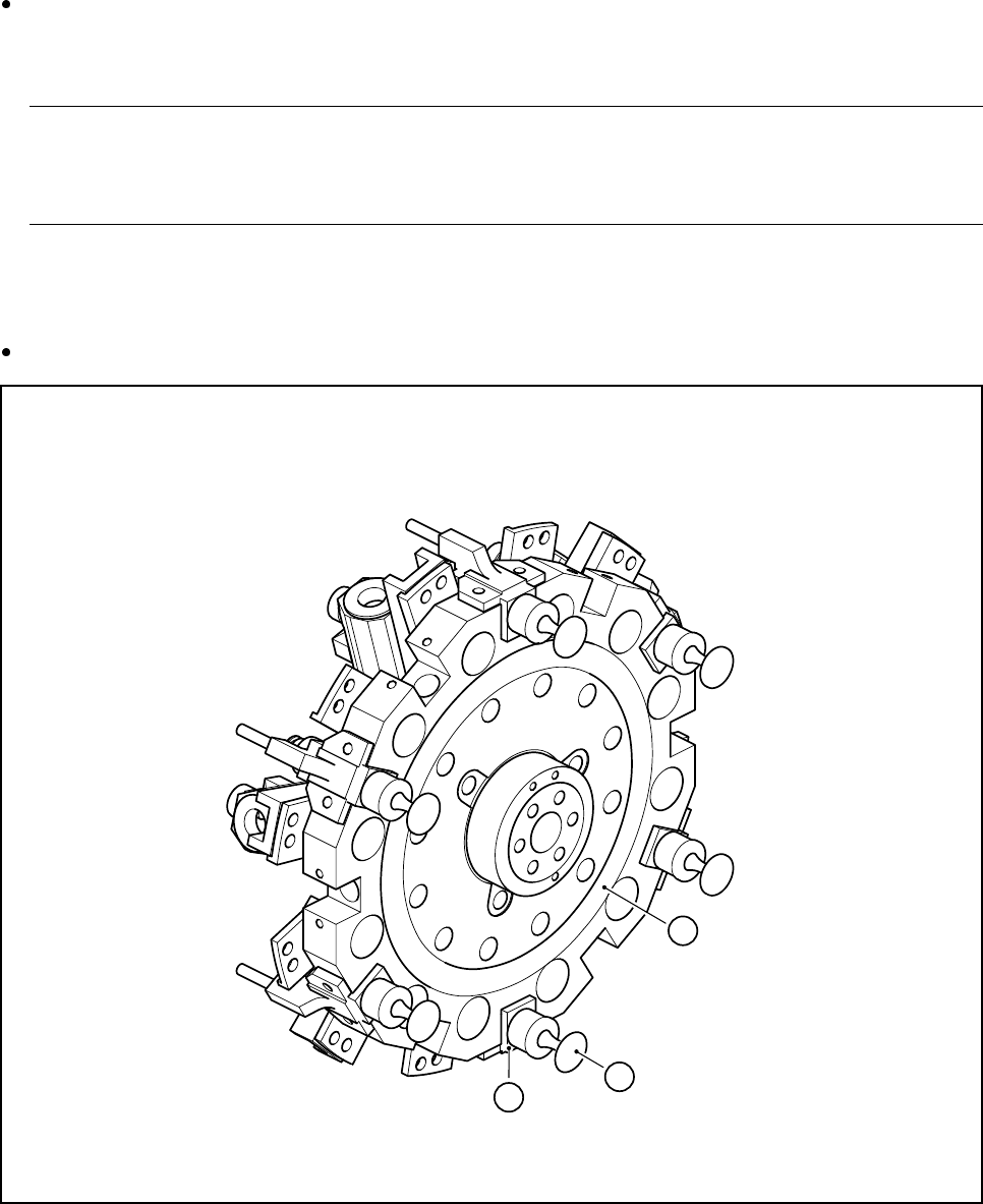
– To remove the valve plunger, it has to be in star position 1. You also have to be able to easily access the
valve plunger head with your fingers.
Take the valve plunger head3 (see Fig. 9.7.9) with your thumb and your forefinger and pull the valve
plunger out of the valve casing 2 (see Fig. 9.7.9). You will initially feel a slight resistance. The valve
plunger can then be pulled out easily.
NOTE
Do not use any pliers to pull out the valve plunger since this could damage the outside of the valve
plunger head.
9.7.6.2 Cleaning the Valve
Clean the hole in the valve casing 2 (see Fig. 9.7.9) with the plastic brush (
Ø 6)
.
Fig. 9.7.9 Star, complete
- Key to Fig. 9.7.9
1 Star, complete 2 Valve casing
3 Valve plunger
1
3
2
9 Maintenance SIPLACE 80S-20/F4/F4-6/F5 User’s Manual
9.7 6x Revolver Head (8000) Edition 03/98 from Software Version SR.404.xx
9 - 88
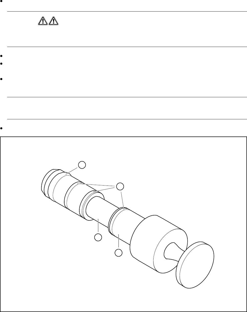
Clean the valve plunger
1
(see Fig. 9.7.10) using a dry, clean cloth.
WARNING
Never use alcohol, cleaning agents or solvents to clean the valve plungers. Cleaning the o-rings using
these agents can result in malfunctions during placement operation (due to vacuum problems).
In particular, ensure that the recess 2 (see Fig. 9.7.10) of the valve plunger is free of grease.
Using a little ISOFLEX® TOPAS® NCA52 grease on a lint-free cloth, lightly grease the o-rings 3 and the
Viton o-ring 4. Make sure that some of the grease is also applied to the recess.
Push the valve plunger 3 (see Fig. 9.7.9, page 9 - 87) back into the valve casing 2 (see Fig. 9.7.9, page
9 - 87) until it reaches the stop.
In particular ensure that the plunger is not skewed when inserted, since this could damage the hole in the
valve casing.
Finally carry out a vacuum test.
Fig. 9.7.10 Cleaning and greasing the valve plunger on the 6x head
- Key to Fig. 9.7.10
1 Valve plunger 2 Recess must be free of grease
3 Lightly grease o-ring and recess 4 Viton o-ring 3x1 (black)
1
2
3
4