80S-2080F480F4-680F5 User’s Manual.pdf - 第687页
11 Station Extensions/Options SIPLACE 80S-20/F4/F4-6/F5 User’s M anual 11.12 Nozzle Changer for the 6x R evolver Head Edition 03/98 f rom Software Version SR.404.xx 11 - 90
SIPLACE 80S-20/F4/F4-6/F5 User’s Manual 11 Station Extensions/Options
Edition 03/98 from Software Version SR.404.xx 11.12 Nozzle Changer for the 6x Revolver Head
11 - 89
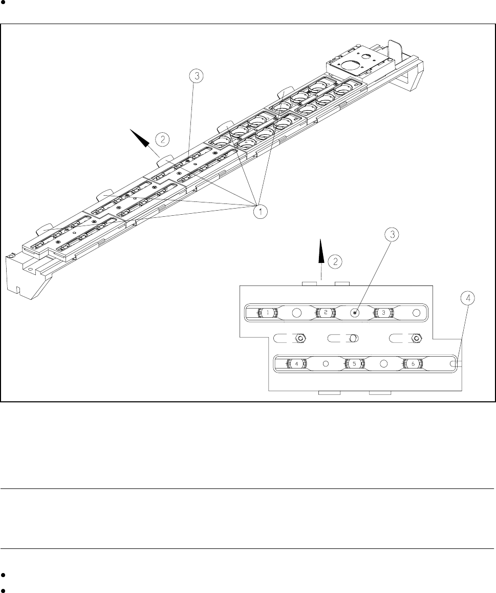
11.12.6 Changing the Magazine
To remove the magazine, push the spring hooks to the side and lift the magazine out of the support.
Fig. 11.12.5 Changing the magazine
- Key to Fig. 11.12.5
1 Spring hook 2 Push the spring hook to the side
3 Fiducial 4 Latching groove
PLEASE NOTE
The magazine must be inserted so that the side with the fiducial points towards the spring hook. There is a
latching groove on the other side of the magazine.
To insert the magazine, insert the side with the groove on the support.
Push the spring hook to the side and click the entire magazine onto the support. Release the spring hook.
The spring hook must latch in place.
11 Station Extensions/Options SIPLACE 80S-20/F4/F4-6/F5 User’s Manual
11.12 Nozzle Changer for the 6x Revolver Head Edition 03/98 from Software Version SR.404.xx
11 - 90
SIPLACE 80S-20/F4/F4-6/F5 User’s Manual 11 Station Extensions/Options
Edition 03/98 from Software Version SR.404.xx 11.13 Transferring PCB data
11 - 91
11.13 Transferring PCB data
11.13.1 Description of the functions
The ’Machine options’ menu now includes a ’Transfer PCB data’ option. The purpose of this function is to
increase the line performance of placement systems. At the
first
placement station, all the PCB measure-
ments are recorded and the associated data concerning fiducials, circuit images, ink spots, etc, is calculated,
stored and passed on to the subsequent stations. This means that it is only necessary to determine the data
for two fiducial positions at the next stations. A position correction for the PCB to be processed is then carried
out on these two fiducial positions at each station. It is thus unnecessary to measure the entire PCB again
when measuring circuit images, ink spots, etc.
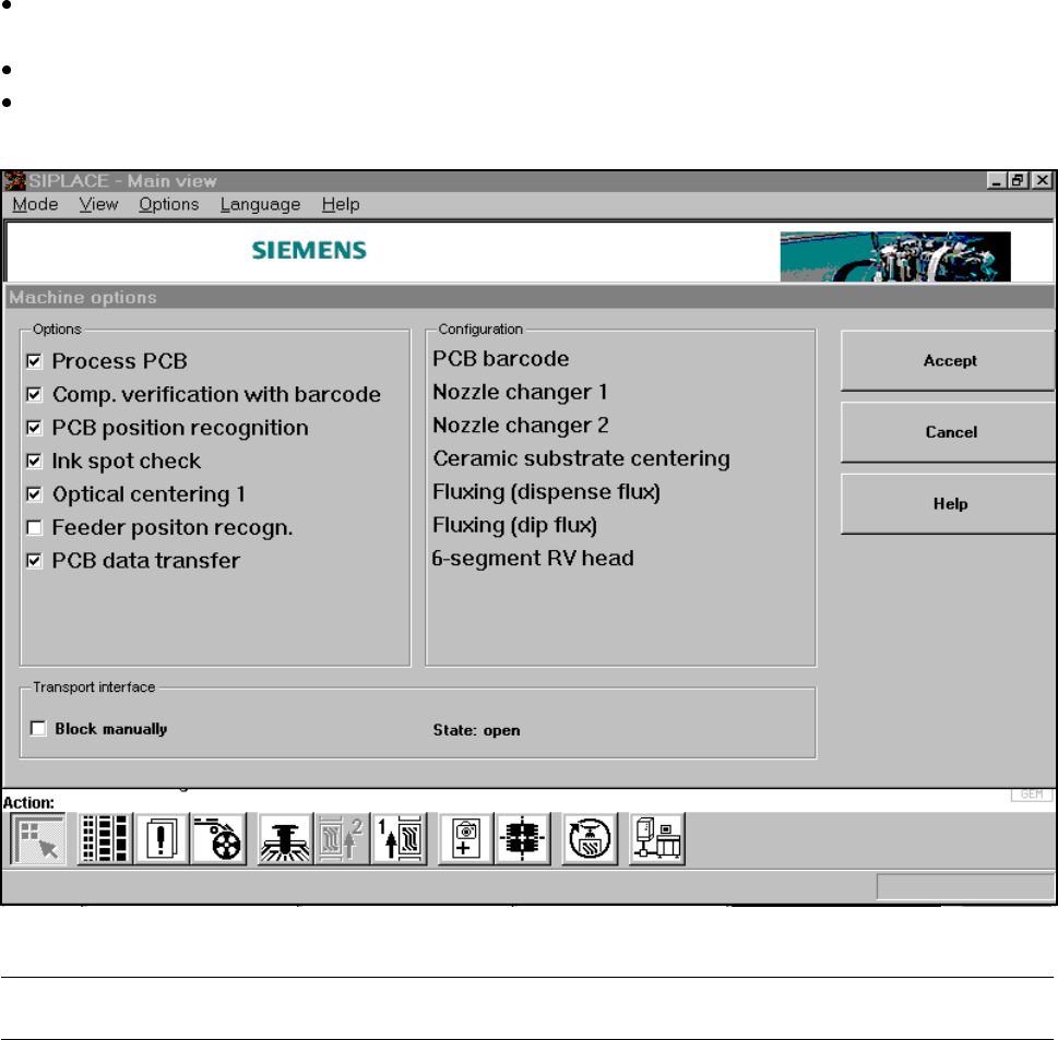
11.13.2 Activating the Transfer PCB data option
Click on the ’Machine options’ button in the main view.
The ’Machine options’ window will appear.
In the ’Options’ box, activate the ’Transfer PCB data’ option for the station concerned.
Click on the ’Accept’ button.
The ’Transfer PCB data’ is now active.
Fig. 11.13.1 Machine option: Transfer PCB data
PLEASE NOTE: Transfer PCB data can only be used in conjunction with a PCB barcode reader.
❒