2OM-1733-005w_F8.pdf - 第126页
2OM-1733 2-1-4 1204-001
2OM-1733
2-1-3
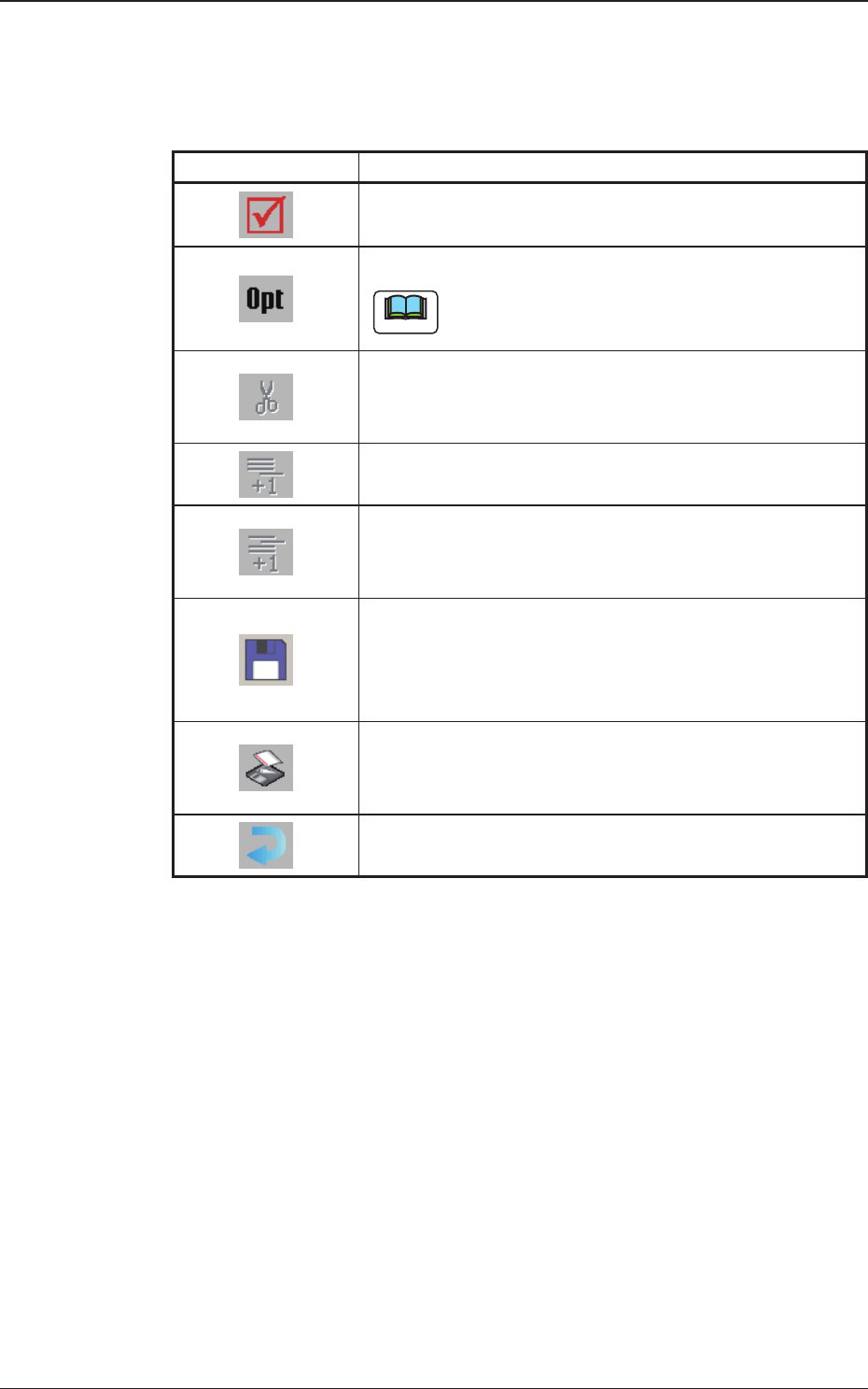
[3] Tool Bar
The operation commands that can be executed in the data edit window, are
collectively displayed as icons.
Table 2B1-2
Icons Description
When selected, the data is checked.
Whether or not the data is completed, is checked.
When selected, the data is optimized.
Note
When pressed, the machine components are searched.
When selected, the data within the selectable range is
cutout.
When selected, an empty line is added to the last portion.
An empty line is added to the last line.
When selected, an empty line is added to the cursor
position.
An empty line is added to any position.
When selected the current le is saved.
The le currently in the course of editing, is saved.
In the case of new le, the le is to be saved with a new
name.
When selected, the le is saved with a new name.
The le currently in the course of editing, is saved with a
new name.
When selected, the window is returned.
The "Product." window is returned.
[4] Data Edit Window
The test data edit window, numerical value entry window or selective entry
window is displayed based on the data selected in the pattern program menu.
[AC] Button :
When pressed, the data in the course of the entry operation,
is cleared.
[BS] Button :
When pressed, a backspace is given to the data in the course
of the entry operation.
[Bk.] Button
[Fr.] Button :
When pressed, the displayed window is changed.
[Set] Button :
When pressed, the entered numerical value or selected item
is set.
1212-002
1. Outline of Pattern Program

2OM-1733
2-1-41204-001
2OM-1733
2-2-1
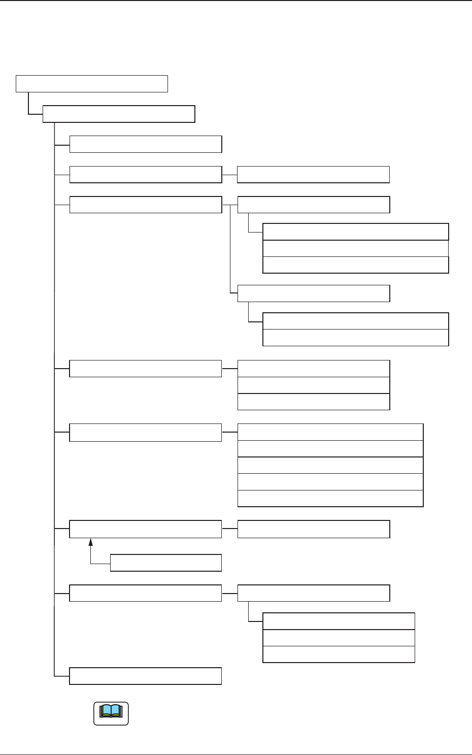
2. Composition of Pattern Program
The pattern program is composed of the following data.
Pattern Program (Chapter 2)
Pattern Program
Common SET (3.1)
PCB (3.2)
Operation (3.3)
Control (3.4)
PL Head/Nozzle (3.5)
CMPNT PL (3.6,F01)
Component Library
Component ID
Placement (3.7,G01)
HDLG/PL (3.8)
Function (C01)
Mark (C02)
Operation (C03)
Set-up (C04)
Control (D01)
PCB Locate (D02)
Transfer speed (D03)
Nozzle Place (E01)
Block 1(2)
Nozzle Stk 11 (E02)
Offset (G02)
P-Data (G03)
O-Data (G04)
PCB (B01)
Un
Support Pin (C05)
PCB Recog
Set-up
Nozzle Stk 12 (E02)
Nozzle Stk 21 (E02)
Nozzle Stk 22 (E02)
Note
(3.1) to (3.8) and (B01) to (G04) show the Nos. to be referred to.
Fig. 2B2-1 Composition of Pattern Program
1212-002
2. Composition of Pattern Program