2OM-1733-005w_F8.pdf - 第291页
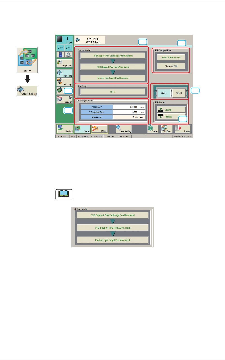
2OM-1733 6-4-1 4. "CNVR Set-up" Window The "CNVR Set-up SPRT-PINS" window appears. [1] [2] [5] [4] [3] [6] Fig. 2F4-1 [1] "Set-up Mode" Group Box Each function in this group box can be used …

2OM-1733
6-3-41205-001
2OM-1733
6-4-1
4. "CNVR Set-up" Window
The "CNVR Set-up SPRT-PINS" window appears.
[1]
[2]
[5]
[4]
[3]
[6]
Fig. 2F4-1
[1] "Set-up Mode" Group Box
Each function in this group box can be used for the replacement work of the
support pins.
Note
The display varied depending on the product model pattern program
setting.
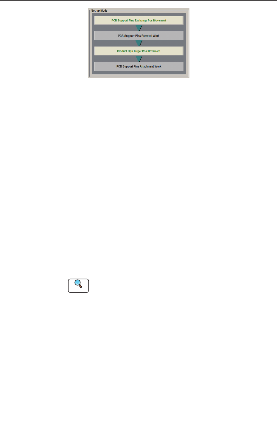
Fig. 2F4-2
When "Enable (Automatic Change)" has been set up for "Support Pin
Setting", the above is displayed.
Graphic
Development
1212-002
4. "CNVR Set-up" Window
2OM-1733
6-4-2
Fig. 2F4-3
When "Disable (Manual Change)" has been set up for "Support Pin Setting",
the above is displayed.
[2] "Noz Chg." Group Box
[Reset] Button
When this button is pressed and within 10 seconds, the [START] button on
the operation panel is pressed, the support pins are housed in the nozzle area.
[3] "PCB Support Pins" Group Box
[Reset PCB Sup.Pins] Button
When the [START] button is pressed in 10 seconds after this button, the
support pins are housed in the stock area.
[Stkr.Area Edit] Button
In the case that the PCB support pins are to be moved manually or an error
occurs, the stock area parameters are edited.
When the [Stkr.Area Edit] button is pressed, the "Stkr.Area Edit" window
appears.
Reference
Refer to "4.4.1 Stkr.Area Edit Procedure" for the details of the
"Stkr.Area Edit" window.
[4] PCB Locate Section Select Buttons
When pressed, the PCB positioning section on the side where the setup
operation is to be performed, is selected.
[Side L] Button :
PCB Locate L Section
[Side R] Button :
PCB Locate R Section
1212-002
4. "CNVR Set-up" Window