2OM-1733-005w_F8.pdf - 第128页
2OM-1733 2-2-2 2.1 Composition of Common SET Note This data is used in the dual transfer operation (option). 2.2 Composition of PCB Data The set parameters are used to set the PCB size and reference, etc. B01 PCB T able …
2OM-1733
2-2-1
2. Composition of Pattern Program
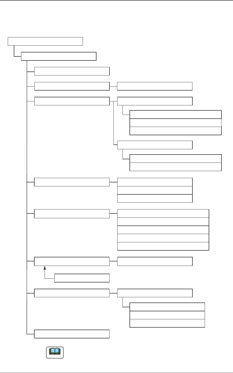
The pattern program is composed of the following data.
Pattern Program (Chapter 2)
Pattern Program
Common SET (3.1)
PCB (3.2)
Operation (3.3)
Control (3.4)
PL Head/Nozzle (3.5)
CMPNT PL (3.6,F01)
Component Library
Component ID
Placement (3.7,G01)
HDLG/PL (3.8)
Function (C01)
Mark (C02)
Operation (C03)
Set-up (C04)
Control (D01)
PCB Locate (D02)
Transfer speed (D03)
Nozzle Place (E01)
Block 1(2)
Nozzle Stk 11 (E02)
Offset (G02)
P-Data (G03)
O-Data (G04)
PCB (B01)
Un
Support Pin (C05)
PCB Recog
Set-up
Nozzle Stk 12 (E02)
Nozzle Stk 21 (E02)
Nozzle Stk 22 (E02)
Note
(3.1) to (3.8) and (B01) to (G04) show the Nos. to be referred to.
Fig. 2B2-1 Composition of Pattern Program
1212-002
2. Composition of Pattern Program

2OM-1733
2-2-2
2.1 Composition of Common SET
Note
This data is used in the dual transfer operation (option).
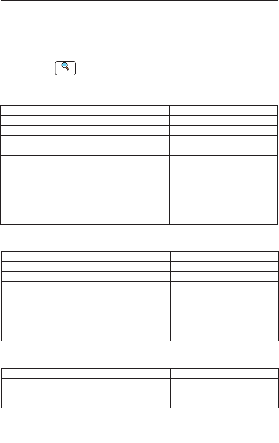
2.2 Composition of PCB Data
The set parameters are used to set the PCB size and reference, etc.
B01 PCB
Table 2B2-1
Items Ref. No.
PCB Size
X (Horizontal), Y (Vertical), T (Thickness)
B01_01
PCB origin offset
X (Horizontal), Y (Vertical), Z (Angle),
X/Y Coordinate Angle,
X-Direction, Y-Direction, Z-Direction
B01_02
PCB height offset B01_03
Placement Reference B01_04
Component Library Placement Offset B01_05
PCB Warpage B01_06
Lot Name B01_07
Comment 1 and Comment 2 B01_08
1212-003
2.1 Composition of Common SET
2OM-1733
2-2-3
2.3 Composition of Operation Data
The set parameters are used to manage the overall pattern program data.
This data is composed of the PCB data, the PEC recognition data, the PEC
recognition mark data, and the setup data.
Reference
Refer to "3.3 Operation in Chapter 2" for the details of earth item
C01 Function
Table 2B2-2
Items Ref. No.
PEC recognition function C01_01
Global (Zones 1 through 5) C01_02
Image C01_03
Local C01_04
Zones 1, 2, 3, 4 and 5
#1 X [mm] (Horizontal) and Y [mm] (Vertical)
#1 Mark Code
#2 X [mm] (Horizontal) and Y [mm] (Vertical)
#2 Mark Code
#3 X [mm] (Horizontal) and Y [mm] (Vertical)
#3 Mark Code
C01_05
C02 Mark
Table 2B2-3
Items Ref. No.
Mark No. C02_01
Mark Type C02_02
Mark Sizes D1 [mm], D2 [mm] and D3 [mm] C02_03
Window Size [mm] C02_04
Mark Image C02_05
Mark Level C02_06
Angle [deg] C02_07
Lighting Level Coax, Ring, Option C02_08
C03 Operation
Table 2B2-4
Items Ref. No.
PEC Recognition Set C03_01
Beam C03_02
Sequence C03_03
1212-002
2.3 Composition of Operation Data