2OM-1733-005w_F8.pdf - 第141页
2OM-1733 2-3-7 1212-003 3.2 PCB Example of Jig PCB Usage The gure below shows that the upper surface of a PCB is lower than the PCB upper surface reference. If "PCB Upper Surface Reference + a" is set as an of…
2OM-1733
2-3-6
Z-Direction
Select one of the following options to determine the Z angular orientation of
the placement coordinate reference point.
Same
: Select this when the angular orientation is the same as that
of the machine coordinates.
Opposite
: Select this when the angular orientation is opposite,
compared with the direction of the machine coordinates.
(B01_03)
PCB height offset [mm]
Set an offset value as a nozzle descending distance based on the upper
surface of the PCB in the component placement section. This offset value
applies to all components in the pattern program.
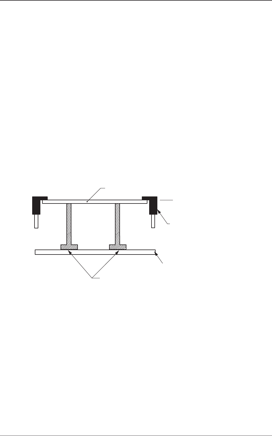
Normal Cases
Set "+0.000" (zero) in the text box.
The gure below shows that the upper surface of a PCB is maintained by
the PCB support pins at the PCB upper surface reference.
PCB
PCB Upper Surface
Reference
Chute
Backup Pin
Backup Table
Fig. 2B3-7
1212-002
3.2 PCB
2OM-1733
2-3-71212-003
3.2 PCB
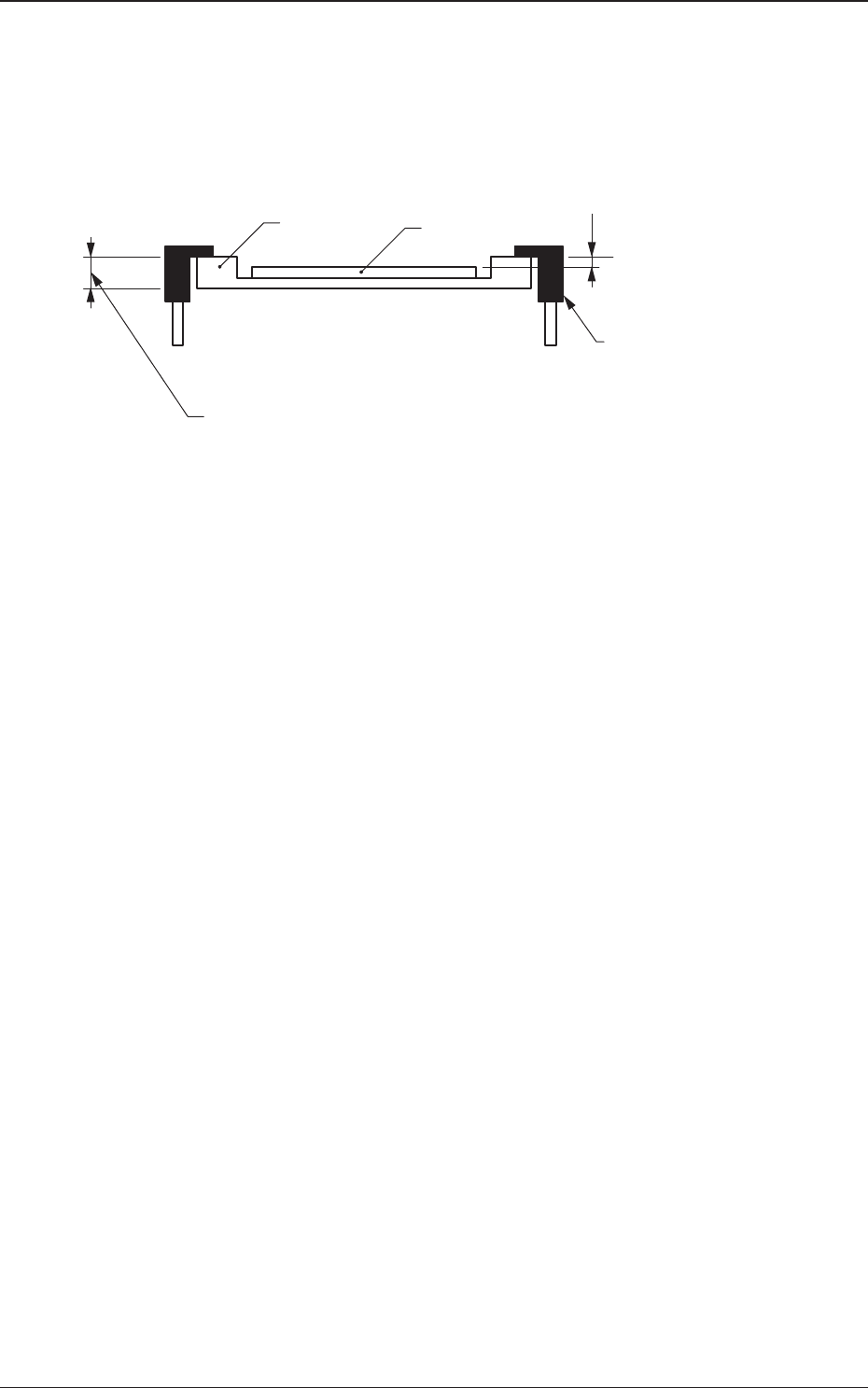
Example of Jig PCB Usage
The gure below shows that the upper surface of a PCB is lower than the
PCB upper surface reference.
If "PCB Upper Surface Reference + a" is set as an offset value at this time,
components can be placed correctly on the PCB.
a
T (Thickness)
Jig PCB
PCB
PCB Upper Surface
Reference
Chute
Fig. 2B3-8
2OM-1733
2-3-8
(B01_04)
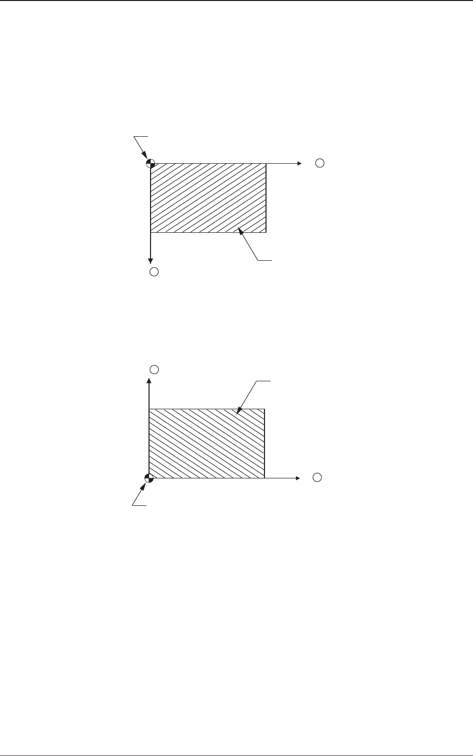
Placement Reference
Set the PCB positioning reference in this text box. The reference must be
specied according to the input and output machines.
Rear Left
: The placement coordinate reference is based on the rear left
side and specied as follows.
X +
Y +
Placement Coordinate Reference (No)
PCB
Fig 2B3-9
Front Left
: The placement coordinate reference is based on the front left
side and specied as follows.
X +
Y +
Placement Coordinate Reference (No)
PCB
Fig. 2B3-10
1212-002
3.2 PCB