2OM-1733-005w_F8.pdf - 第133页
2OM-1733 2-2-7 2.5 Composition of Placement Nozzle Data The set parameters are used to place the nozzles onto the specied positions on the head (Place Head/Noz No.). Reference Refer to "3.5 PL Head / Nozzle" f…

2OM-1733
2-2-6
Items Ref. No.
UP
MOVE
1st Speed DCLR SET
2nd Speed DCLR SET
Vac. Ctrl. clelayed starts
Vac. Wtg. Timer
Z clamp waiting time
D02_09
DN
MOVE
1st Speed DCLR SET
2nd Speed DCLR SET
Damaged Vac. Wtg. time
Backup axis DNstart CLY
D02_10
D03 Transfer speed
Table 2B2-9
Items Ref. No.
Transportation speed SET D03_01
Transfer speed
Carrier, Stage inside, Output
D03_02
Component Deviation Control
Carrier, Stage inside, Output
D03_03
Control the stop position
Carrier, Positioning 1, Positioning 2, Output
D03_04
1403-004
2.4 Composition of Control Data
2OM-1733
2-2-7
2.5 Composition of Placement Nozzle Data
The set parameters are used to place the nozzles onto the specied positions on
the head (Place Head/Noz No.).
Reference
Refer to "3.5 PL Head / Nozzle" for the details of each item according to the
reference Nos. (Ref. Nos.).
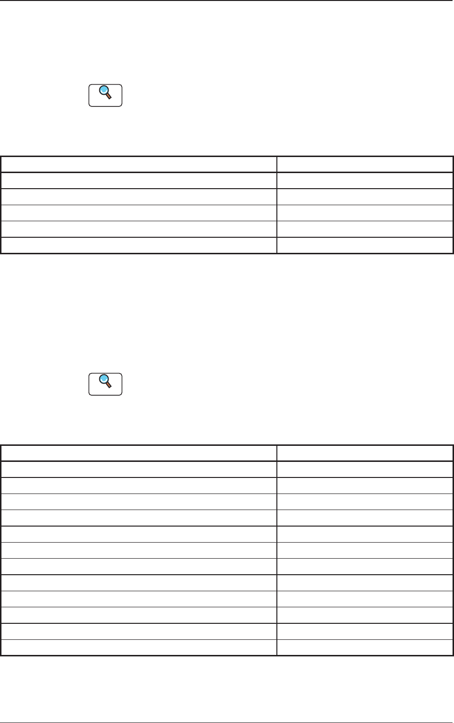
E01 Nozzle Place
Table 2B2-10
Items Ref. No.
Nozzle Place (E01-01)
Nozzle Stk 11 (E02)
Nozzle Stk 12 (E02)
Nozzle Stk 21 (E02)
Nozzle Stk 22 (E02)
2.6 Composition of Placement Feeder Location Data
The set parameters are used to determine which feeder slot Nos. (Fdr No.) various
types of components should be allocated to.
Component IDs (types of components to be allocated) must be specied for each
individual feeder bases.
Reference
Refer to "3.6 CMPNT PL" for the details of each item according to the reference
Nos. (Ref. Nos.).
F01 CMPNT PL
Table 2B2-11
Items Ref. No.
Fdr No. (F01_01)
Component ID (F01_02)
C (Control Command) (F01_03)
Comment (F01_04)
Feeder Fixed (F01_05)
Feeder Alternate (F01_06)
Fdr No. (F01_07)
Component Library Comment (F01_08)
Dir [deg], Carrier Data Type, Width [mm] (F01_09)
Fd. Pitch [mm] (F01_10)
Used Parts (F01_11)
Nozzle Type (F01_12)
1212-003
2.5 Composition of Placement Nozzle Data

2OM-1733
2-2-8
2.7 Composition of Placement Data
The set parameters are used to place the components (IDs in the placement feeder
location data) on the points with the specied coordinates in the designated
direction.
One step is allocated for each component to be placed.
Reference
Refer to "3.7 Placement Data" for the details of each item.
G01 Placement
Table 2B2-12
Items Ref. No.
Un (G01-01)
Offset Data (G02)
Offset (G02)
Unit Control (G02_01)
Offset
X [mm], Y [mm], Z [ ° ], H [mm]
(G02_02)
Unit PCB Fiducial (G02_03)
Recog Coord
X1, Y1, X2, Y2
(G02_04)
Fiducial Mark
FM1, FM2
(G02_05)
D-Data (G03)
P-Data (G03)
PNo. (G03_01)
X [mm], Y[mm] (G03_02)
Z [ ° ] (G03_03)
H [mm] (G03_04)
Component ID (G03_05)
Fdr. No. (G03_06)
Symbol (G03_07)
C (G03_08)
Comment (G03_09)
ADJ X,Y (G03_10)
O-Data (G04)
Ono. (G04_01)
X [mm], Y[mm] (G04_02)
Z [ ° ] (G04_03)
H [mm] (G04_04)
C (G04_05)
Comment (G04_06)
B-X, B-Y (G04_07)
1212-003
2.7 Composition of Placement Data